
* Modern radar technology has evolved in a number of ways that the founders of the technology would have been hard-pressed to imagine, for example "synthetic aperture radars (SAR)" for ground imaging; "multimode radars" that can switch between a number of functions; "active array radars" consisting of an array of RF modules; and "over the horizon" radars with extraordinary range.
* As mentioned, early bombing radars were able to give very rough maps of terrain that could identify bodies of water and large structures. A radar that could actually provide an image of the ground was developed in the late 1950s in the form of "side looking airborne radar (SLAR)".
The basic idea was to mount a long radar antenna, usually in a "canoe" fairing under an aircraft, that generated a narrow beam to the sides. The echo returns were recorded on a filmstrip that gave a map under the aircraft's flight path. The maps were surprisingly detailed given the relatively primitive technology, but they had some quirks of perspective: the scans of terrain were performed to the sides of the flight path of the aircraft, and to no surprise, that didn't result in the same kind of map geometry that would have been obtained from a mosaic of pictures of the same terrain taken by an aircraft flying directly over each segment of the terrain. The SLAR images similarly suffered from "shadowing", where high ground hid terrain from the radar, resulting in the masked terrain showing up as a black shadow in the filmstrip.
The pioneering radar ground surveillance system was the Grumman OV-10 Mohawk, which was used by the US Army with considerable success during the Vietnam War as a battlefield reconnaissance aircraft. The Mohawk could carry film cameras and either an infrared sensor or a Motorola AN/APS-94 SLAR, with the SLAR antenna carried under the fuselage in a long rectangular box. SLAR imagery was recorded on a long filmstrip on board the aircraft, or could be relayed to a ground station to be similarly recorded there.
* During the 1960s and 1960s, development work focused on a much more sophisticated version of SLAR, known as "synthetic aperture radar (SAR)". With traditional SLAR, the antenna sent out a pulse and got a return, which was recorded on film. With modern SAR, the antenna sends out multiple pulses to cover the same ground as the aircraft carrying the antenna moves along. The data from pulse returns is stored and processed to give a combined image. This creates an effective antenna length equivalent to the distance the antenna moves during the series of scans, a "virtual array" that provides much higher resolution than a traditional SLAR with its "real array".
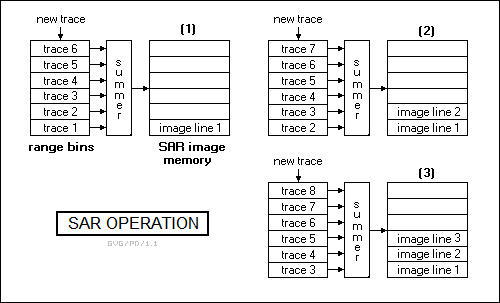
SAR is based on an extension of the concept of range bins. Suppose a SAR system has a "queue" of sets of range bins, say eight for example purposes. The SAR system sends out eight radar pulses, with the return from each being stored in one of the sets of range bins in the queue. All eight sets are then summed to average out the noise and enhance the actual echoes, resulting in one line of a radar image that has much more clarity than the single return from a SLAR real array.
Now, the SAR sends out a ninth pulse. Since there are only eight sets of range bins, the data from the oldest of the previous eight scans in the front of the queue is discarded, the other seven sets are "moved up" in the queue, and the return from the new scan is stored in the empty entry in the back of the queue. These eight sets of values are then summed to generate the next line of the SAR image. This scheme is repeated for all successive scans.
The effective antenna length of a SAR is limited by the phase shift of the returns from the target; as the phase shifts, it becomes more and more difficult to sum the returns, though processing can compensate for the phase changes to an extent. It is also possible to use a phased-array antenna to "focus" on a specific target in a "spotlight" mode to reduce phase shifting and improve resolution. Of course, the processing system can perform GMTI processing, useful for combat targeting. Modern "SAR-MTI" systems can be programmed to spot targets in motion.
SAR can give high-resolution maps of ground features, but it doesn't provide much in the way of enhanced resolution for moving targets. There is an associated scheme known as "inverse SAR (ISAR)", where the rotational motion of the target is used to improve resolution.
Incidentally, early SARs used optical processing systems based on lenses and photographic films. This was an inflexible approach, demanding that the observing platform operate at a specific height over the terrain to be imaged; it was best used with satellites that orbited at known altitudes.
BACK_TO_TOP* The integration of computing with radar was a true revolution in radar technology, resulting in modern radars that compare to their World War II ancestors in much the same way that a 21st-century personal computer compares to a mechanical desk calculator.
In the early days of radar, tracking targets was a manual task. In control centers for air-defense networks or on warships, the raw sensor readings were reported to workers who would mark the positions of targets on a transparent board. With a modern digital radar, the computer now handles the job of displaying radar data to the operator, and so the data can be displayed in any format that is convenient -- in a B-scope or C-scope plot, overlaid on a map, and with "symbology" such as text or geometric figures to help interpret the data. The display system can even in principle give a three-dimensional color scene representation, along the lines of a "video game for real".
Digital capabilities allow a radar to change its functionality at will, resulting in the modern "multimode radars" carried by combat aircraft. A multimode radar might provide modes for:
Modern multimode radars may incorporate "low probability of intercept (LPI)" features that prevent the radar from tripping off alarm systems in a target. LPI features include:
However, techniques such as jumping around in frequency -- or "frequency agility" as it is known -- do make it difficult to generate coherent signals for pulse Doppler operation.
Another advanced feature in modern multimode radars is to match radar "signatures" of an unidentified aircraft target against a stored library to determine what type of aircraft it is. Such a "non-cooperative target identification (NCTI)" capability allows a fighter to determine if a target is highly likely to be a hostile even when it's "beyond visual range (BVR)" so that it can be engaged with long-range AAMs. Of course, NCTI requires a lot of processing power. Modern implementations leverage off of "machine learning" technology, using brainlike "neural networks", that are "trained" by being exposed to large numbers of radar images of potential targets and told what the targets are. Their ability to distinguish targets improves with the number of tagged images.
Typical US multimode radars for fighters have included the Hughes AN/APG-63 and improved AN/APG-70 for the Boeing F-15; the Hughes AN/APG-65 and later AN/APG-73 for the Boeing F/A-18; and the Hughes AN/APG-66 and later AN/APG-68 for the Lockheed Martin F-16. The Northrop Grumman B-2 flying-wing bomber carried the Hughes AN/APQ-181 radar, with some similarities to the AN/APG-70 of the F-15 but tailored for the navigation and bombing roles. In fact, all these radars share some common technologies and features, but have different power capabilities and form factors to adapt them to their particular aircraft platform.
Naval helicopters also may be fitted with multimode radars to provide navigation assistance, hunt for targets, and cue missiles; a well-known example was the British Ferranti Seaspray radar, used on the Westland Lynx helicopter. The fact that the Seaspray wasn't so different from a fighter multimode radar is emphasized by the fact that it was modified for use in the BAE Sea Harrier jumpjet strike fighter as the "Blue Fox". It was admittedly something of a cheap-and-simple solution -- with the Sea Harriers later refitted with the Ferranti "Blue Vixen", which was a state-of-the art fighter multimode radar.
A digital radar can become part of an integrated system, for example with an aircraft radar linked to infrared and other sensors, defensive countermeasures, and database information, and a computer performing "sensor fusion" to give the pilot a picture of the current situation. The scheme can be extended to other platforms using radio datalinks, with an AEW aircraft monitoring an intruder on its radar and sending the tracking data to a fighter moving to intercept the intruder. The fighter pilot would see the radar data on the fighter's display, but the fighter would not be transmitting radar pulses that gave away its own position.
BACK_TO_TOP* The latest thing in airborne multimode radars in the 21st century is a follow-on to the concept of the phased array, known as the "active electronically scanned array (AESA)". A traditional "passive" phased array antenna consists of a grid of antenna elements. An AESA takes this concept a step further, using a grid of hundreds or thousands of small "transmitter-receiver (TR)" modules that are linked together by high-speed processors.
Each TR module has its own transmitter, receiver, processing power, and a small spikelike radiator antenna on top. Each TR module can be programmed to act as a transmitter, receiver, or radar. The TR modules in the AESA system can all work together to create a powerful radar, but they can do different tasks in parallel, with some operating together as a radar warning receiver, others operating together as a jammer, and the rest operating as a radar. TR modules can be reassigned to any role, with output power or receiver sensitivity of any one of the "subsystems" defined by such temporary associations and proportional to the number of modules.
Along with flexible operation, an AESA has other advantages. For one, it degrades gracefully: any TR modules that go bad can simply be disabled and ignored, with the others taking up the load. An AESA can also be designed to be "scaleable", with the same system adapted to different aircraft and other platforms by simply changing the number of TR modules to fit the space available. The same basic technology can be carried on a drone, a fighter jet, or a large surveillance aircraft. Raytheon has even performed work on an AESA the size of an athletic field, to be carried on a high-altitude surveillance airship.
One of the pioneering AESA designs was the AN/APG-77, designed in the early 1990s for the Lockheed Martin F/A-22 Raptor fighter. The AN/APG-77 consisted of an array of about 2,000 TR modules. Operating as an RWR, it could detect an enemy aircraft's radar from distances of up to 460 kilometers (250 nautical miles). Operating as a radar, it could acquire an enemy fighter at distances of up to 220 kilometers (125 nautical miles), while the enemy will find its LPI radar signal difficult to detect.
Between dealing with active threats, the AESA collects information on the electronic order of battle in the operational area, locating electronic systems, classifying them, and alerting the pilot to possible threats or high-priority targets. It can also be used for communications.
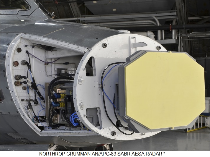
AESA radars have been introduced for older fighters, such as the AN/APG-82 for the F-15 and the AN/APG-83 "Scalable Agile Beam Radar (SABR)" for the F-16. These radar systems are more capable than the AN/APG-77. The AN/APG-77 used a first-generation TR module called a "brick", because it is about the size and shape of a standard building brick, with a spikelike "radiator" antenna on top. In contrast, the second-generation AESA systems are based on an improved T/R module known as a "tile", since it about the size and shape of a ceramic tile about 5 centimeters (2 inches) on a side. One side of the tile contains an antenna, while the other contains miniaturized electronics.
Most of the signal electronics are based on gallium arsenide "monolithic microwave integrated circuits (MMIC)", although developers are looking at gallium nitride, silicon germanium, and silicon carbide farther down the road. T/R bricks and tiles are often packaged as a "suitcase" containing four or more modules for more powerful radar arrays. Improvements in technology has not only reduced the size led to smaller TR modules, they have resulted in more power-efficient and cheaper units.
TR modules are actually built in a range of formats for operation in different bands. High-frequency X-band modules are assembled into tight, compact arrays to provide a fighter with a high-resolution targeting radar, while low-frequency L-band or S-band modules are assembled into less dense arrays for long-range detection. Incidentally, the length of the radiator spike on top of a TR module determines the frequency range that an AESA can deal with. A long radiator will cover a wide band, and a short one will cover a narrow band.
A variation on the AESA is a "hybrid" system known as an "AESA-Fed Reflector (AFR)", in which a relatively small active array is placed at the effective focal point of a large passive reflector. The scheme gives some of the flexibility of the AESA, along with a large aperture size.
While it might seem that AESA radars are really only appropriate for military use, once the cost comes down they should prove useful in civilian applications as well. Airports, for example, often use several different types of radars; with AESA, all they need in principle is one, which not only reduces the cost of the radar system but also the cost of powering the radar system, which is not necessarily trivial. LPI signal-processing techniques would also be useful in such an application -- not to conceal the radar signal, there would be no need to do that, but to reduce output power and so further cut the cost of powering the system.
BACK_TO_TOP* It is possible to build a radar that has "over the horizon" range, obtained by "bouncing" or "backscattering" radio waves off the ionosphere, the ionized layer at the top of the atmosphere. Such an "over the horizon backscatter (OTHB)" radar operates in the low HF band, since microwave frequencies will punch right through the ionosphere.
Even at HF frequencies, OTHB is tricky. The exact properties of the ionosphere can vary, sometimes wildly, over the course of a day, and even when it's stable it's not like a radio "mirror", crisply reflecting radio waves back down towards the ground, instead tending to smear out and scatter pulses. Of course, along with a range of thousands of kilometers comes extremely weak returns. At best OTHB can do no more than give the general location of a target, making it only useful for early warning and the like. OTHB requires a good deal of sophisticated processing, and it wasn't practical until the late 1950s. Given the long wavelengths, an OTHB antenna array is a sprawled business, stretched out over kilometers. Some OTHB radars have used FM-CW to maximize signal energy, and such systems require separate transmit and receive antenna arrays. In any case, they are always Doppler radars, since they necessarily have to sort through heavy ground returns.
In the mid-1950s, the US Naval Research Laboratory (NRL) NRL and the US Central Intelligence Agency (CIA) developed the first OTHB system, codenamed "Chapel Bell". It was strictly a demonstrator, but it led to the secret operational "Earthling" OTHB built in Pakistan to keep an eye on Soviet rocket launches in Kazakhstan. Earthling became operational in 1961, but relations between Pakistan and the US then gradually deteriorated, with Earthling finally being shut down in 1965. The next year, the CIA began operation of a more powerful OTHB in Taiwan, codenamed "Checkrote".
The Air Force also built an OTHB system, designated "AN/FPS-118", to give long-range warning of Soviet bomber attacks. A prototype system was developed in the 1970s, leading to operational deployment in the 1980s. There were two systems, one to overlook the Pacific and the other to overlook the Atlantic. The radars were bistatic, with the triple transmitter arrays and triple receiver arrays at separate sites about 160 kilometers (100 miles) apart. The West Coast system had the transmitters in Oregon and the receivers in California, while the East Coast system was set up in Maine.
The AN/FPS-118 systems were more or less shut down after the end of the Cold War, ironically not long after they reached full operational capability, though at last notice the East Coast system was still in partial operation. The AN/FPS-118 OTHBs were FM-CW systems with a continuous (of course, they were CW radars) power output of a megawatt each, operating in the HF band from 5 MHz from 28 MHz (60 meters to 10.7 meters). Range was highly variable, but could be up to thousands of kilometers. The AN/FPS-118s were among the most powerful radars ever built.
The US Navy also built a "relocatable" OTHB, the "AN/TPS-71", which could be packed up and moved if necessary, though calling it "portable" would be an exaggeration. Three AN/TPS-71 systems were built and at last notice were keeping an eye out for drug traffickers from America's coasts.
* The Soviets built an OTHB system, which US intelligence codenamed "Steel Yard", though details are not surprisingly unclear. It interfered with the transmissions of American amateur radio enthusiasts (HAM) from 1976 into 1989. After the fall of the Soviet Union, Steel Yard was revealed as the "Duga-3" radar system, being part of an element of the national missile early warning system. Two were put into operation, the first in Ukraine near Chernobyl, the site of the infamous nuclear disaster, and the other in eastern Russia. Like the US AN/FPS-118, the Duga-3 was a bistatic system, with widely separated transmitter and receiver.
The HAMs called Duga-3 the "Russian Woodpecker" for the 10 Hz drumming sound of the interference. Some HAMs, who called themselves "Woodpecker Hunters", were fond of driving bogus signals on the transmit band back into it. An informal network of hunters would coordinate their activities, "ganging up" on the Woodpecker, and though they had no way of knowing how effective they were, they figured they had scored when the OTHB changed bands immediately in response. Nobody's certain that the Soviets ever really noticed, though the returns to an OTHB are so faint that even a low-powered jamming signal might have an effect.
Incidentally, some conspiracy paranoids have claimed, for reasons clear only to themselves, that the Duga-3 was actually a Soviet "global mind-control experiment". Less popular, if just as reasonable, suggestions were that it was a weather-control system or a beacon for aliens. No informed analysis of the known structure of the Duga-3 antennas or the signals transmitted by them suggests they were anything but OTHB radar systems.
The Australians put an advanced OTHB system named the "Jindalee" into operation in 2000. It used half the power of the AN/FPS-118 but has much better range, due to its improved design and greater processing power. The French ONERA defense research agency set up a very interesting prototype OTHB radar named "Nostradamus" in 2005; it features 288 antennas in a three-branch star array that handles both transmit and receive functions. The antennas are "conical", each consisting of a mast with a hoop around it, strung with aerials running from the mast to the ground. It is used for both surveillance and ionospheric research. An operational follow-on system is under consideration.
* It is also possible to build an over the horizon radar using what is known as a "ground wave". Radio waves tend to bend or "diffract" around edges or curves, and HF waves can actually bend over the horizon, forming a "surface wave" or "ground wave". The scheme is known as "OTH-SW" and is similar to OTHB, requiring large arrays and a lot of signal processing. It doesn't have as much range as OTHB, and is really only useful for oceanic surveillance.
Raytheon Canada and the Canadian military developed such an OTH-SW, designated the "HF-SWR-503", to help spot smugglers and illegal fishing boats, as well as assist in search and rescue operations. It is mainly designed to track ocean traffic, but can also track aircraft. It consists of an array of monopoles 660 meters (2,165 feet) long, with the monopoles spaced at about 50 meters (164 feet), corresponding to half the wavelength of the radar's 6 to 3 MHz operating band.
The array has a field of view of 120 degrees and can track targets to the limit of Canada's 370-kilometer (200-nautical mile) oceanic economic exclusion zone (EEZ). It can obtain positions accurate to within hundreds of meters. Raytheon stated that a similar array could be used to track low-flying cruise missiles if it operated at a frequency of 15 to 20 MHz. Raytheon is now working with the Canadians to develop a next-generation variant of the radar. India has been interested in OTH-SW radars to help defend coastal areas from terrorist attacks coming in from the sea.
BACK_TO_TOP* Bistatic radars have been around since the beginning of the technology. As mentioned, many early fixed-station radars were bistatic, with transmitter and receiver at separate locations, and SARH missiles like the Sparrow are effective bistatic systems as well. The bistatic scheme works for the Sparrow, even though the missile is moving, because it doesn't try to estimate range; it just follows the radar reflections to the target. The missile would be hard-pressed to use these signals to estimate range, because it has no clear notion of when the transmitter sent the pulse or where the transmitter was when it did. However, work is currently underway on advanced bistatic radars that use datalinks and synchronization systems to allow one platform to receive radar echoes from pulses sent out by another. The advantage of this scheme is that it would allow platforms to sense targets without generating emissions themselves and giving themselves away.
This leads to the notion of a purely "passive" radar system. The Germans actually developed such a thing during World War II, if under very special circumstances. The system, known as "Kleine Heidelberg", intercepted pulses from the British Chain Home floodlight radar system, and then picked up echoes off targets from those pulses with a directional antenna. This scheme was only workable because Chain Home was a floodlight system. If it hadn't been, the Kleine Heidelberg receiver would have only picked transmitter pulses when the transmitter was pointed directly at it. The positions of the Chain Home sites were also precisely known; there was no way to use such a simple approach with radars more advanced than Chain Home.
The introduction of computing power to radar has revived the concept. In the 1990s, Lockheed Martin demonstrated a passive radar named "Silent Sentry". It was based on a "passive coherent location (PCL)" scheme that monitored both direct and echo signals from one or more commercial FM radio or VHF/UHF TV stations, and used intensive parallel processing from computer workstations to sort out the information.
The Silent Sentry used a fixed array measuring some 2.4 x 7.6 meters (8 x 25 feet), mounted on the side of a building, with the radar monitoring local FM radio broadcast stations to track airliner traffic at a nearby airport. Silent Sentry could track targets with a radar cross-section of ten square meters (107 square feet) from 200 kilometers (125 miles) away. The flat array had a viewing angle of 105 degrees in azimuth and 50 degrees in altitude. A system with a 360-degree azimuth view would use four arrays. From the point of view of the radar electronics system itself, a passive radar is fairly simple, with the real heavy lifting performed by sophisticated signal processing.
The scheme wasn't accurate enough for targeting. However, FM signals tend to hug the ground through diffraction as surface waves, and in fact the computer system behind the radar included a terrain database to help compensate for the effects of surface features. This low-altitude capability made the Silent Sentry potentially useful for identifying cruise missiles or drug smugglers.
Work on passive radars is also underway in Europe and Israel. Passive radars are seen as a way to complement, not replace active radar, helping plug holes in a radar screen. Passive radars are not immune to jamming; broadband jamming will wipe out the signals they use to track targets, and they are just as easily deceived by decoys as any other radar.
* Detecting low-flying cruise missiles is a high priority in military radar development. Such systems are based on radars operating in two or more frequency bands. Low-frequency UHF or L-band radars are better than high-frequency radars for picking up low-RCS targets at long range, but they suffer from noise interference and low resolution. Modern signal procession algorithms can cut through the noise, but for resolution the low-frequency radar has to be ganged with a higher-frequency S-band or X-band radar.
Such a multi-frequency radar system would also be able to penetrate jungle and forest canopies to identify targets hidden underneath. The biggest problem is that low frequency radars also tend to be extremely bulky and difficult to fit into an aircraft of any reasonable size, and no such system is anywhere near introduction.
* Finally, work is underway to build "ultrawideband" radars with long-wavelength ground penetration ability to detect mines and unexploded ordnance. A number of efforts are being pursued along this line, with experiments using airships to hunt down mines. Presumably an operational system would include some sort of projectile or energy beam weapon to actually destroy the mines from a safe distance.
There has also been consideration of "quantum radars", based on a scheme called "quantum entanglement (QE)". Quantum physics shows that it is possible to generate pairs of particles that have linked complementary properties that remain linked over a distance, and so knowing one of these properties of a local particle means a distant particle has the complementary property.
There's been thought of using QE to develop radars with new capabilities, but so far nobody's got so far as a proof of concept on doing it. There's been a big push towards "quantum technologies" in general as of late, but it's becoming obvious that it's somewhat over-hyped.
BACK_TO_TOP