
* Radar technology came of age in World War II, with the technology development during that period laying the groundwork for further elaboration in the postwar period. This chapter outlines the evolution of radar technologies in this era.
* The sort of simple pulse radar system described in the previous chapter was more or less available at the beginning of World War II, and was used on ground sites and on ships. The war led to improved radar technologies and an explosion of radar applications and types.
One of the early improvements was to build a radar that could automatically sweep around the sky to search for intruders. The early floodlight systems could cover a wide sector of the sky, but as mentioned they were inefficient. A simple steerable radar with an A-scope display was more efficient, but it had to be manually steered to find a target. Building an improved radar that could be swept around 360 degrees was a bit tricky, since it implied that the electrical connection between the antenna system and its associated electronics had to freely rotate, and designing reliable "rotary couplers" was troublesome.
It also implied a different type of display, the "plan position indicator (PPI)", AKA the "polar plot indicator". The PPI is a circular display, with a sweep rotating around the center in sync with the transmitter antenna, and the return for a particular angle displayed along the display sweep. As the sweep rotates around the center of the display, it paints an image of what the radar "sees" all around it. The display uses has a "long-persistence phosphor" that allows the image to linger after the sweep has passed, fading away just before the sweep comes around to refresh the image. A PPI display can be thought of as something like an A-scope being spun around in a circle, following the spin of the antenna, with a single A-scope trace on each radius of the circle.
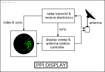
The PPI is the popular concept of a radar display, commonly seen in TV shows in which a mysterious or dangerous intruder is moving closer to the center of the display, where the heroes are, with every sweep. (In some shows, they use a PPI even when the radar doesn't have a rotating antenna.) In the early days, the radar did little processing on the return echoes, and so it was up to the operator staring at the PPI to figure out what the display actually said. It wasn't necessarily the case that there was a simple bright blip where the intruder was; there would often be sources of "clutter" in the radar sweep, such as flights of birds, swarms of insects, and other obstructions to the radar beam.
Incidentally, the time it takes for the antenna to rotate 360 degrees and for the sweep to correspondingly move all the way around the display is referred to as the "update rate". One of the classic examples of such a radar was the US Navy "SG" shipboard radar, which was a 3 GHz / 10 centimeter system with a horizontal parabolic antenna. It could provide a "map" of threats and obstacles around a vessel on its PPI display.
* One of the issues, if not necessarily a problem, with the "search radar" scheme described above is that it gives the range and azimuth to the target, but not its altitude -- it is a "two-dimensional" or "2D" radar. That was okay if the search radar was being used by a ship or a coastal site to track other ships, since their altitude was of course at sea level, but not so good if the search radar was tracking aircraft.
The search radar didn't really need to determine altitude by itself. Its major function was just to provide a warning, and to do that it was best designed to generate a long-range beam in a "fan" configuration that was very tall and thin, with the radar essentially throwing out a cylindrical "wall" of radio waves with each sweep, through which intruders had to pass. Once an intruder was located, a separate, steerable "height-finder" radar could be pointed in the direction given by the search radar to determine the intruder's altitude. The height-finder radar generated a beam that was very short but wide, exactly the opposite of the search radar. The two radars effectively formed "crosshairs" that pinned down the precise coordinates of the target. Height finders were often designed to "nod" up and down to search for a target. The US Navy "Mark 22" or "Lil' Abner" radar was a classic example of such a height-finding radar, with a vertical antenna like a peel of a slice of an orange, and nodding operation.
Of course, over the long run improvements in radar technology allowed development of a single radar that could determine both the azimuth and altitude of an intruder. Such a radar is of course known as a "three-dimensional" or "3D" radar.
BACK_TO_TOP* The search radar / height finder radar combination was fine for vectoring fighters against intruders, but antiaircraft guns needed a single radar that could zero precisely in on a target and track it.
As mentioned earlier, a radar's accuracy is a function of the angular width of its beam. A radar beam can be thought of as something like a radar "spotlight", with a very narrow spotlight beam able to more precisely pin down the direction of a distant target than a broad one.
There was a way to get accuracy much better than the actual width of the beam. Radar antennas typically emit electromagnetic radiation in the form of a teardrop-shaped "lobe", tapered at the sides and broad at the tip. Trying to pin down a target in a single broad lobe is troublesome -- but suppose the radar transmitter actually has two antennas, toed out slightly relative to their mutual centerline, and the transmitter alternates sending pulses, sending a pulse with one and then the other consecutively. The radar operator can then steer this antenna array until the alternating returns are the same size, meaning the target is on the centerline. Since the edges of the lobes are relatively sharp, this allows relatively precise location of the target. The error signals provided by the difference in the two lobes can be used to control servo motors that guide the radar along the track of the target automatically: if the signal is stronger in one lobe than the other, the antenna is steered in the direction of the stronger lobe until the two signals balance.
This scheme is known as "lobe switching" or just "lobing", and it is a form of what is called "angle tracking". Some early anti-aircraft radars used horizontal and vertical lobe switching to target intruders. A good example was the US "SCR-268" anti-aircraft radar, which was developed alongside the SCR-270 search radar mentioned in the previous chapter and shared some of the same technology. The SCR-268 operated at 100 MHz / 1.5 meters. It was somewhat clumsy-looking, featuring a transmit antenna, a vertical lobing receiver antenna, and a horizontal lobing receiver antenna, all mounted together on a single gun-type mount. The transmit antenna was in the form of a 4 x 4 array of dipoles; the vertical receiver antenna was a 2 x 6 rectangular array of dipoles, mounted with its long axis vertical on the right; and the horizontal receiver antenna was a 6-by-4 array of dipoles, mounted with its short axis vertical on the left. The SCR-268 had a beam width of 2 degrees in both the horizontal and vertical directions, and a maximum range of 36 kilometers (23 miles).
As awkward as it looked, the SCR-268 was actually a fairly good piece of gear by the standards of the time, and would remain in first-line service for gun laying and searchlight direction late into the war -- its retirement mostly being driven by the fact that the Germans had figured out how to jam it. Some shipboard radars used to direct naval guns for firing on surface targets got by with only horizontal lobe switching.
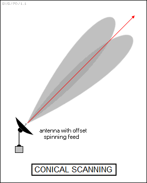
* Anti-aircraft radars were then refined to a more sophisticated scheme for lobe switching, known as "conical scanning". This involved a parabolic dish antenna with a radio "feed" element that was slightly offset from the centerline. The feed element was rotated at a low rate to generate pulses slightly skewed from the centerline, with the dish steered until the returns were all equal.
Some of these radars also had "helical scanning", which sounds the same but was actually something different, meaning that the entire radar dish spun around in a helical pattern while it was searching for a target, something like the way a height-finder radar nodded up and down. Once the targeting radar found a target, it stopped helical scanning and used conical scanning to pin down its precise location.
Originally, anti-aircraft targeting radars simply gave aim points for anti-aircraft guns. The scheme was quickly improved so that the error signals from the tracking radar not only steered the radar antenna, they steered the gun automatically as well. Since the gun had to "lead" the target to score a hit, it couldn't point in exactly the same direction as the radar antenna, with an analog computer in the loop calculating the proper lead for the gun. The result was an improvement in lethality by an order of magnitude or more. The classic example of such a gun-laying radar was the US "SCR-584", which was a microwave set with a circular parabolic dish using helical and conical scanning. It was linked to a heavy antiaircraft gun through an analog computer system.
The technology was refined in the postwar period, one of the notable examples being the well-known and highly effective Soviet-Russian ZSU-23-4 "Shilka" tracked anti-aircraft vehicle, with quadruple 23-millimeter automatic cannon in a turret mount, guided with speed and accuracy by an automatic radar fire-control system.
BACK_TO_TOP* If fighters were sent up against intruders in daylight and clear weather, ground-based radars could generally get them close enough to perform an interception by eyeball. However, there was little chance of finding an intruder visually at night or in bad weather, and so night fighters carried their own radars, allowing them to target intruders after being vectored to their vicinity by ground search radars.
Night fighter or "airborne intercept (AI)" radar had limited maximum range -- and early sets had long pulse widths, giving the radars a long minimum range, meaning they had to be near a target to find it with radar and then could easily lose it while trying to close in on it. Another problem with these early night fighter radars was that they operated at long wavelengths, with the result that it was difficult to obtain a narrow beam.
The problem with such a wide beam was not really limited angular accuracy; night fighter radars used lobe switching and conical scanning to obtain useful targeting precision with relatively long wavelengths, obtaining enough accuracy to find a target even with a wide beam. The major difficulty with all early pulse radars was that they had no "discrimination". If the radar pulse hit something, anything, the echo came back and showed up on the display. That meant that if a hostile aircraft was low to the ground, reflections from the terrain or "ground clutter" kept it invisible to radar. A wide beam meant that ground clutter remained a problem at relatively high altitudes, lost in the noise; the need to produce an AI with a narrow beam with an antenna that could be carried in a night fighter was one of the drivers of microwave radar.
The classic AI radar was the US "SCR-720", a 3 GHz / 10 centimeter set used in the Northrop P-61 Black Widow night fighter. The SCR-720 remained in first-line service into the early 1950s in improved versions.
* Work on radars that could be carried by patrol aircraft to hunt for ships and submarines in the dark and bad weather went on in parallel with the development of AI radars. Such "air-to-surface vessel (ASV)" radars were useful because a ship target was big enough to be picked out of the clutter returned from the surface of the water, though unsurprisingly the clutter got worse when the weather was worse and the waves were higher. Microwave radars were also useful for ASV, since their higher resolution allowed them to better pick out targets. Systems were developed that linked into the ASV radar to automatically release bombs during low-level attacks on shipping.
* Following the development of ASV radars, other radars were developed for targeting air strikes against cities and other area targets on land. These were very crude bombing aids, since they really couldn't do much more than distinguish between dry ground and bodies of water, and only worked well when the target could be identified by lakes or the confluence of rivers. Once again, microwave radars were preferred since they gave a higher resolution image.
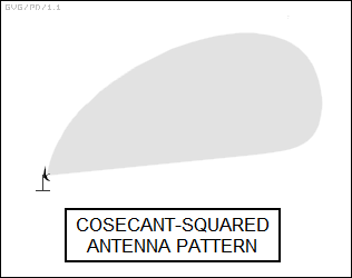
Such bombing radars used a PPI display to give a map of the terrain below. The radar had to compensate for the fact that radar echo returns farther away from the center of the display were fainter, distorting the radar "image", and so the receiver sensitivity was adjusted to be greater at higher angles. This is known as "cosecant-squared" operation, since that's the mathematical function used to determine the gain function. It was actually implemented by modifying the antenna to provide the cosecant-squared pattern, with the antenna designed with different inner and outer curvatures. The cosecant-squared configuration was also used in naval search radars, to allow the radar to pick up targets at higher altitudes while avoiding pickup of sea-surface clutter.
A classic example of such a bombing radar was the "H2X", a 10 GHz / 3 centimeter radar that was built as a follow-on to the ground-breaking British "H2S" radar. The H2X, or "AN/APS-15", was also used as an ASV radar, replacing the cosecant-squared antenna with a more conventional antenna useful for search.
* The first "airborne early warning (AEW)" radar systems were introduced at the end of the war. Since a search radar was blocked by the horizon and suffered from surface clutter reflections, the idea was to put a radar in an aircraft that could fly at a high altitude to give it a wide view and greater freedom from ground clutter. The radar itself was less of a challenge than the issues of relaying the radar information to the ground station or aircraft carrier that was operating under the AEW "umbrella".
The grandfather of AEW radars was the US "AN/APS-20" radar, which was initially deployed at the end of World War II, on a modified Grumman Avenger torpedo bomber with a bulging radome under the belly. The AN/APS-20 would actually remain in service, with improvements, into the Vietnam War era and, to a lingering extent, well beyond. Its best-known platform was the RC-121 Warning Star, a military modification of the Lockheed Super Constellation four-engine piston airliner, with the AN/APS-20 in a belly radome and a height-finder radar in a dorsal radome.
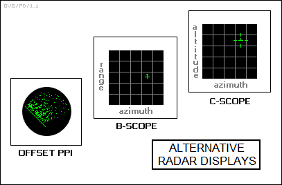
* Incidentally, although so far this discussion has only discussed the A-scope and PPI displays, other radar display formats were developed:
* The invention of radar to track aircraft immediately led to the issue of how to distinguish "friendly" aircraft from "hostile" aircraft. If an aircraft were just a blip on a PPI scope, there was no telling from that information if it was an enemy that had to be destroyed before it was too late -- or if it was a "friendly" who had got lost, and was now in great danger from its own side.
The answer was to create a scheme, known as "identification friend or foe (IFF)" that allowed electronic identification of a target. A radar site or a fighter could have a radio system known as an "IFF interrogator" that sent a specific signal to an aircraft. The aircraft would, in turn, have a radio system called an "IFF transponder" that picked up the interrogator signal and gave a proper coded response to identify itself as friendly. Incidentally, IFF was also used on ships.
IFF is a tricky issue, since an enemy can not only use IFF to impersonate a friend, but can also trick friendly aircraft or ships into giving away their presence by interrogating IFF. This is the IFF challenge: protecting one's own IFF while trying to compromise the enemy's.
Early IFF systems were actually interrogated directly by radars, but as radars evolved into a wide range of different types, that meant that an IFF transponder had to be able to respond to all the different types of radars. That not only made the IFF transponder complicated, it made it easier for an adversary to compromise the IFF system. The solution was to develop specialized interrogator systems designed to be used as an accessory on a radar, with an IFF antenna "piggybacking" in some way on the radar antenna. This scheme was embodied in the British "Mark III" IFF transponder, which became an Allied standard during the war.
* The idea of having a transponder that replied only to specific radar signals was a dead end for IFF -- but had its uses elsewhere, leading to the parallel development of "radar beacons". These beacons were just transponders that could be used to mark an airfield, or could be carried by advance parties to mark paratrooper landing zones or amphibious landing beaches.
The same approach could be used to give the distance to a fixed station. The idea is conceptually very simple: an interrogator sends a radio pulse to a transponder, which then replies, and the round-trip time is determined to give the range between interrogator and transponder. The approach is very similar to radar, and in fact such a radar beacon scheme is often called a "secondary radar". The British developed a precision bombing system based on secondary radars named "Gee-H" that permitted highly accurate "blind bombing" -- at least for aircraft with a line of sight to a fixed base station in friendly territory.
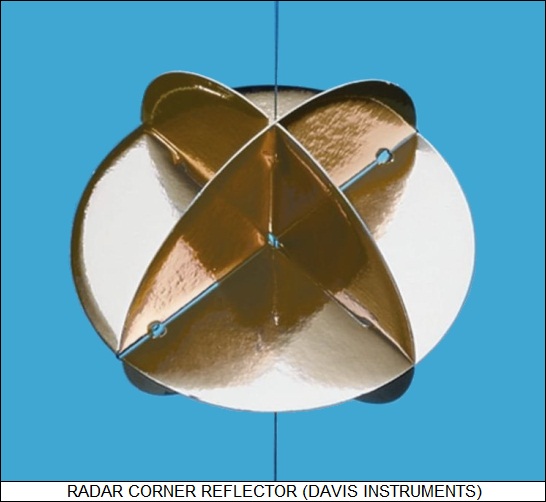
* As noted above, radar beacons were often used to mark drop zones and landing beaches. The advantage of a radar beacon was that it did not advertise its presence to the enemy, only "speaking when spoken to." There were times when that wasn't really a concern, for example to mark rocks that were to be avoided by a landing force, and a cheaper marker could be used, called a "corner reflector", or more formally "radar signature enhancement device". This was just some panels of metal joined together in a kite-like configuration to create nice sharp corners that could reflect radio waves.
The problem with this type of corner reflector was that it was somewhat bulky and inconvenient. After the war, another type of signature enhancement device was developed, known as a "Luneberg lens". Electromagnetic waves may have different propagation velocities in different types of solids, with the propagation velocity given by an "index of refraction". If an electromagnetic wave passes through materials with different indexes of refraction, the wave will be partly reflected, with the amount of reflection given by the size of the difference in the index of refraction. A Luneberg lens is a sphere with a graded index of refraction, making it very reflective to radar. It is compact, and is often carried by robot aircraft used as decoys or training targets. Incidentally, a Luneberg lens is still sometimes called a "corner reflector" -- despite the fact that spheres don't have corners.
BACK_TO_TOP* Simple continuous wave detectors and radars were discussed in the previous chapter. During the war, "proximity fuzes" were developed for anti-aircraft gun shells, allowing the shells to be triggered when they passed within a lethal radius of a target. Coupled with radar-guided automatic tracking, the proximity fuze helped boost the lethality of antiaircraft guns by a large factor. Such fuzes could be thought of as CW radars, but that's stretching the definition of the term "radar": they simply generated a continuous radio signal and at close ranges, the "near field", the presence of a target would "load down" the oscillator generating the signal and changing its frequency of oscillation, which triggered the fuze. The term "proximity detector" seems more suitable.
True CW radars were used in World War II and continue to be used. The most significant application is for guiding anti-aircraft missiles. Some early surface-to-air missiles (SAM) used two pulse radars, one to track the target and the other to track the missile, with course corrections provided to the missile under radio control. This was a bit inefficient, and it proved simpler to put a radar receiver in the missile. One of the early approaches was to have the missile carry a radar receiver, in the tail, that would stay on the track of a narrow continuous beam generated by the targeting radar. This scheme was known as "semi-active beam-riding (SABR)", or just "beam riding", and was used on early versions of the pioneering American "Sparrow" air-to-air missile (AAM).
Beam riding was quickly replaced by a more effective scheme, "semi-active radar homing (SARH)", in which the missile homed in on radar reflections off the target. Later Sparrow variants used SARH. The launch platform provided continuous-wave illumination for the receiver in the missile, with the launch platform and the missile forming in effect a continuous-wave bistatic radar system. Since the missile had no need to calculate range, the CW scheme was perfectly satisfactory.
* Incidentally, the problem with semi-active AAMs was that the launch aircraft had to keep the target "illuminated" with its radar while the missile was on the way, meaning the aircraft had little freedom to maneuver. The obvious answer was to develop a complete radar guidance system, with transmitter, receiver, and homing circuits, to fit into the AAM. An aircraft could launch an AAM with such an "active seeker" and then take evasive action, or in other words such a missile had a "fire and forget" capability.
That was difficult for the technology of the 1950s. The BOMARC SAM of the late 1950s and early 1960s did have an active seeker, but it was a big machine, essentially a pilotless supersonic aircraft that could carry a nuclear warhead -- a small one, as nuclear warheads go. Many modern SAMs and AAMs, such as the US AIM-120 AMRAAM, the Sparrow's much-improved descendant, do have such a fire and forget capability. The AMRAAM is targeted using the launch platform's radar but cruises to the target area using an autopilot system, then performs the "terminal attack" using the active seeker.
* Another simple radar developed during the war was the "radar altimeter". This was just a pulse ranging radar that could tell how far an aircraft was above ground, bouncing a pulse off the terrain and timing the round-trip from the aircraft and back. However, these simple radar altimeters were only really suited for high-altitude operation. Low altitudes demanded a high PRF, which would have made them very susceptible to ghost echoes. The answer to the problem was a frequency modulated continuous (FM-CW) wave radar.
Radar altimeters are conceptually simple. Imagine a radar that transmits continuously in a cycle, but instead of transmitting at a single frequency, it transmits in a continuously increasing "ramp" of frequencies during each cycle. A receiver synchronized to the transmitter cycle and using a separate antenna can then pick up this continuous signal and determine the frequency of the return to get the range.
There's a catch to FM-CW radar, though it turns out to yield benefits. As mentioned in the previous chapter, a simple CW radar can be used to measure target speed through the Doppler shift. Returns to an FM-CW radar also end up being affected by the Doppler shift, which creates an ambiguity. Suppose the FM-CW radar isn't moving, and it's generating a ramp of rising frequencies. If it transmits a particular frequency at a certain time, then when it receives an echo after a specific delay time with the same frequency there is no ambiguity. The round-trip time of the signal is just the measured delay, and the range is easy to calculate.
However, if the FM-CW radar is moving ahead -- as it might be expected to, if it's installed in an aircraft and pointed forward to the ground -- then the Doppler shift will drive up the frequency of the return. If the return signal comes back with a particular frequency, it's actually a Doppler-shifted return from a transmission at a lower frequency, and the range is actually greater than would be expected from the delay time between transmission and reception of the same frequency. Of course, if the FM-CW radar was moving backward the return would be shifted down in frequency and the range would be shorter, but aircraft do not fly backwards in normal operation.
The way around this is to generate the ramp of frequencies up and down in a triangular fashion. To show how this works, let's assume again that the FM-CW radar is stationary and compare the frequency-versus-time plot for transmit and receive, along with a plot of the difference between the two:
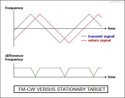
As the illustration shows, for a stationary FM-CW radar, the return signal tracks the transmit signal perfectly, returning with a fixed delay. Notice that at any single time on the plot there is a constant difference between the transmit and receive frequencies, except for the short window between the time the transmit signal changes direction and receive signal follows.
Now let's put the FM-CW radar into forward motion and create the same plot. The return from a stationary target is rendered in light gray to provide a reference.
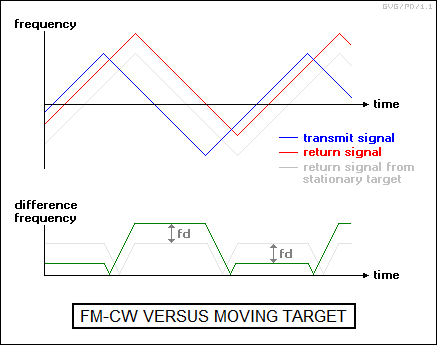
The Doppler shift creates a distinctive offset between the transmit signal and the receive signal. This is because on the rising half of the ramp, the transmit frequency is increasing, and the increased Doppler-shifted return signal is "catching up" with the changing transmit signal; but on the falling half of the ramp, the transmit signal is decreasing, and the increased Doppler-shifted receive signal is "lagging behind" the changing transmit signal.
That means the difference between the transmit and receive frequencies is small on the rising half of the ramp, and large on the falling half of the ramp. An FM-CW radar can use this difference to determine both range and speed. Since the Doppler-shifted component is subtracted on the rising half of the ramp and added on the falling half of the ramp, the range is given by the average difference of the two cycles. This average can be subtracted from the difference in the second half of the cycle to give the Doppler-shifted velocity component, given as "fd" in the diagram.
An FM-CW radar, then, can be used to obtain both altitude and groundspeed. The radar unit is fixed in the nose of the aircraft and pointed down at an angle, with the altitude and speed indicators scaled to compensate. For example, if the FM-CW radar was pointed down at 45 degrees, the altitude scaling factor would be 1/SQRT(2) = 0.7071 and the speed scaling factor would be SQRT(2) = 1.414. Of course, non-level terrain would affect readings. Such FM-CW radars are often called "Doppler navigation", or "CW Doppler", radars.
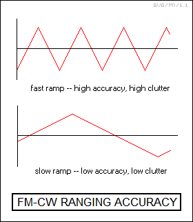
Since there is some inaccuracy in determining the frequency of the return, ranging accuracy is improved if the frequency ramp is steep, since it gives a larger frequency change for a given range, and the inaccuracy of the measurement of the frequency becomes less important. However, if an FM-CW radar is used for ranging a moving target, a rapidly changing frequency ramp becomes a liability, since the returns from ground clutter at different ranges will be over a very wide band that will hide any Doppler shift from a moving target. This means that FM-CW radars used for tracking moving targets must use a slow ramp, resulting in low ranging accuracy.
FM-CW radars could be used with SARH missiles since such a weapon could home in on the reflections from the target, and so the ranging inaccuracy wasn't any real problem. The target was generally out of ground clutter anyway. The well-known US Raytheon Hawk SAM initially used such a scheme. SARH is a declining technology as active radar seekers take over for SAM and AAM guidance, but FM-CW still remains practical and useful for navigation purposes.
BACK_TO_TOP* Almost from the outset, the development of radars was accompanied by the development of technologies to defeat them, or "electronic countermeasures (ECM)". The first approach to defeating radars was to simply jam them.
There were two approaches to jamming: "passive" and "active". Passive jamming involves dispensing lengths of metal, originally paper-backed strips of aluminum, called "chaff" that create radar echoes to hide the aircraft or ship throwing them out. Chaff has to be cut to a length appropriate to a particular radar -- a half or quarter of the radar's operating wavelength -- and chaff designed for a radar operating at one wavelength doesn't work well against a radar operating at a substantially different wavelength. Chaff also has to be dumped in substantial amounts to create an adequate screen against prying radars.
Incidentally, the terminology for chaff can be confusing. Originally, the British dispersed "window", which were strips cut to lengths to jam relatively high-frequency radars. They then also dispersed "rope", which were very long strips intended to jam low-frequency radars. The term "rope" still lingers today, but the term "chaff" is effectively universal.
Active jamming involves a transmitting device that attempts to interfere with the operation of adversary radars. There are two approaches to active jamming: the jammer can either dump out sheer noise and try to drown out the radar, in which case it is known as a "disruptive" jammer, or it can send back false returns, in which case it is known as a "deception" jammer.
Disruptive jamming can be "broadband" -- that is, covering multiple adversary radar bands -- or "narrowband" -- that is, only blanketing a particular radar operational band. Although broadband jamming, also known as "barrage jamming", "covers all the bases", it means that the jammer's output power is spread over multiple bands, and so it's not so effective on any one band. Disruptive jammers are much more typically narrowband or "spot" jammers, being tuned to the band a particular radar is transmitting on.
The simplest form of deception jammer is the "pulse repeater", which sends back amplified copies of a radar return after a delay, to confuse a radar as to the exact location of a target. It can also generate a return copy with no delay to make the target appear to be bigger than it really is -- for example, making a small decoy drone aircraft look like a big bomber.
BACK_TO_TOP