
* This chapter follows up the discussion of the basic laws of thermal physics by considering heat engines, both theoretical and practical, and refrigeration systems.
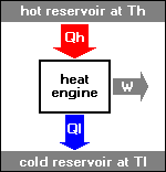
* All mechanical engines are "heat engines", in which heat is converted to work. Automotive engines burn fuel to set the vehicle rolling, while jet engines burn fuel to generate thrust to keep the aircraft flying. Such engines obtain heat from a high-temperature reservoir, derive work from it, and then pass the waste heat on to a low-temperature reservoir. The Second Law of Thermodynamics has particular application in the analysis of the operation of heat engines.
In an "ideal" heat engine, all the heat is converted to work. However, the French engineer Nicolas Leonard Sadi Carnot (1796:1832) demonstrated that there is no way to build a 100% efficient heat engine. In a work published in 1824, Carnot showed that the efficiency of an engine is proportional to the temperature difference between the input and output, and to obtain 100% efficiency the difference would have to be infinite.
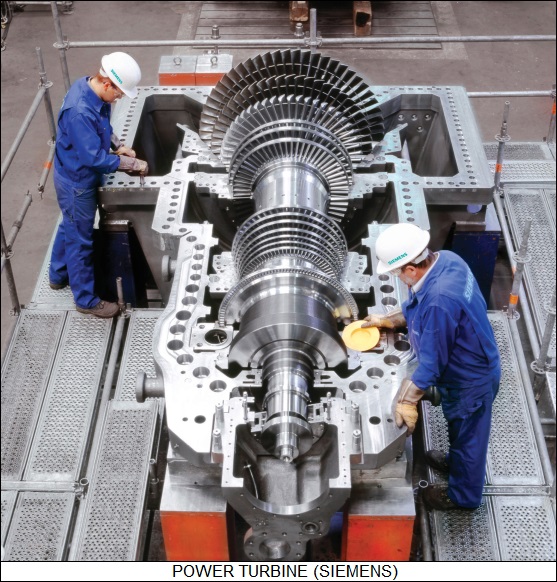
For example, a power turbine uses steam obtained from a boiler heated by coal or oil to drive the turbine, with the exhaust of the turbine consisting of steam that has cooled in the process. Ideally, the heat flowing out of the process is equivalent to the heat flowing into the process minus the work done:
heat_out = heat_in - work
Stated another way:
work = heat_in - heat_out
The efficiency of the engine is given by the proportion of the heat input that is actually converted to work, or:
   _________________________________________________________________________

                    work         heat_in  -  heat_out           heat_out
   efficiency  =  ---------  =  ----------------------  =  1 - ----------
                   heat_in             heat_in                  heat_in
   _________________________________________________________________________
Obviously, the efficiency is maximum when the heat output is zero -- meaning the heat input is completely used up -- but that never happens in practice, and this circumstance is impossible, since it implies that the output has reached absolute zero.
* Carnot established these basic rules by performing a theoretical analysis of a simple "ideal" heat engine that provides a basis for the discussion of all heat engines. The "Carnot engine", as it is now known, is a simple cylinder plugged by a piston and containing a quantity of gas, or "working fluid".
Heat engines operate on "thermodynamic cycles", or steps of thermodynamic processes that operate in a circular fashion. The Carnot engine cycles through four phases of operation, as shown at the left side of the illustration below. The changes in pressure and volume for each phase are shown in the "PV (pressure-volume) chart", also known as an "indicator diagram", at the right side of the illustration.
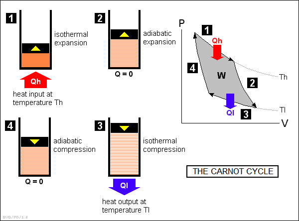
In more detail, the cycle works as follows:
The amount of work W performed by the Carnot engine is given by the area enclosed by the PV curve. This work is equivalent to the input heat Qh less the output heat Ql. As above, this means the efficiency of the Carnot engine is:
efficiency = 1 - ( Ql / Qh )
Carnot's mathematical analysis of his engine showed that the ratio of input and output heat of his engine was the same as the ratio of input and output temperatures, and so:
   _________________________________________________________________________

   efficiency  =  1 - ( Tl / Th )
   _________________________________________________________________________
What this means is that the Carnot engine becomes more efficient as the difference between the input and output temperatures increases. It also shows that an engine can never be 100% efficient since, again, that would imply a Tl of zero degrees Kelvin, which can never be actually reached. Another implication of the Carnot engine is that it requires that heat be drained out of the cylinder for it to work. If the heat were not drained, pushing the piston back in would require as much work as was produced when it was pushed out, and the net work delivered by the engine would be zero.
* The Carnot engine is a theoretical construct, devised simply to provide a starting point for thermodynamic analysis and the understanding of practical engines. The details of operation of practical engines don't quite match this ideal due to factors such as friction, heat losses, the temperature limits of the materials used to build the engine, and so on. However, the basic revelations of the Carnot engine hold true: efficiency is roughly proportional to the temperature difference between engine inlet and outlet, and waste heat must be produced by the engine for it to work.
The fact that engine efficiency is directly proportional to the temperature difference gives an insight into the definition of entropy as heat transfer at a given absolute temperature. As the absolute temperature falls for a heat transfer process, the ability of the heat to do useful work, its "quality", falls or "degrades" as well, or in other words its entropy increases. A quantity of heat transferred at a high temperature has low entropy; the same quantity of heat transferred at a low temperature has high entropy. This is the Second Law of Thermodynamics in action. Over time, in a closed system the transfers of heat occur at lower and lower temperatures, reducing the ability of the system to do work for both artificial engines and natural processes.
BACK_TO_TOP* A number of practical heat engines have been invented and are now in use. One of the most elegant, though one of the least-used, is the "Stirling cycle" engine. This is an "external combustion" engine, meaning that it is powered by an external source of heat. Any reasonably practical heat source can be used, such combustion of gasoline, kerosene, wood or manure, or sunlight focused by a mirror. All the Stirling cycle engine needs to run is a source of heat on one side and a cooling sink on the other.
The Stirling cycle engine's indifference to fuel source is its main advantage, and it is of some use in undeveloped countries where access to fuels is limited. Its disadvantage is that it has a poor "power to weight ratio (PWR)". All other engines in common use can provide the same power for substantially less weight.
The illustration below is an example of a simple (and idealized) implementation of a Stirling cycle engine. It consists of two cylinders, each with their own piston, linked through a gearbox. In this example, steam is fed around the first "hot" cylinder as a heat source, while cooling water is fed around the other "cold" cylinder as a heat sink. The "heads" of the two cylinders are linked by a heat-storage element known as a "regenerator".
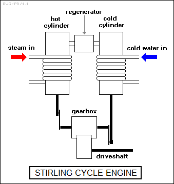
The operation of the engine's gearbox is a bit difficult to follow, since it will bring one piston to a dead stop while moving the other piston, or allowing it to move.
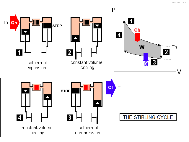
The gearbox steps the engine through a four-part cycle as follows:
This two-cylinder configuration is sometimes known as an "alpha" Stirling engine. In practice, Stirling engines are often built in a "beta" or "displacer" configuration, in which both pistons are in one cylinder, on top of one another and operated by concentric rods, and the regenerator runs up the sides of the cylinder, with ports between the two pistons and above the top piston. The top piston is called the "displacer", since its function is to "displace" the working fluid, while the bottom piston is called the "power piston", since it provides the drive power out of the engine.
The beta Stirling engine's operating principles are exactly the same as those of an alpha Stirling engine, though it is trickier to understand. There is also a "gamma" Stirling engine configuration, which is exactly the same as the beta configuration, except that it is rearranged a bit to avoid the use of concentric rods. The illustration below shows a beta Stirling engine stepping through its cycles, with an idealized Stirling engine shown below to help clarify its operation, along with a gamma configuration engine.
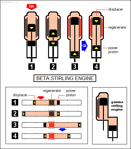
In practice, the gearing system that drives a beta Stirling engine is designed so that a piston may slow down but won't ever actually stop, except for the instant between reversals of direction. This construction "rounds off" the edges of the PV diagram, but otherwise the operation is the same.
* The most popular heat engine in service is the automotive internal combustion engine, known formally as the "Otto cycle" engine and more popularly as the "four-stroke" engine.
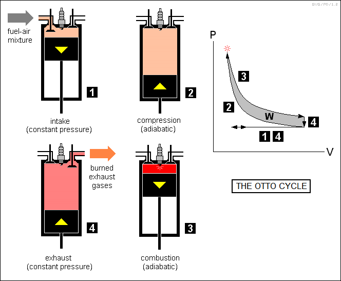
Operation of the Otto cycle is conceptually simple:
Analysis of the Otto cycle engine shows that its efficiency is mostly dependent on the "compression ratio", that is, the ratio of maximum compression of the fuel-air mixture to atmospheric pressure. The greater the compression ratio, the more efficient the engine. However, the Otto cycle engine is limited on the level of compression it can obtain, since at high compressions the temperatures and pressures will cause the fuel-air mixture to ignite spontaneously before the piston reaches the top of its travel. This phenomenon is known as "engine knock".
The "Diesel cycle" engine avoids this problem. It has the same general four-stroke operational cycle as the Otto cycle engine, but uses a fuel injection system to spurt fuel directly into the cylinder at the end of the compression stroke, permitting higher compression ratios. The Diesel engine uses heavier fuels than the Otto cycle engine. It does not use spark plugs, instead using "glow plugs" that are heated and assist ignition of the fuel-air mixture when the compression reaches the proper level.
A second variation on the Otto cycle is the "two-stroke" engine, in which the intake and expansion cycles are combined, as are the compression and exhaust cycles. This means that the two-stroke engine has, in the limit, twice as much power for a given RPM than a four-stroke engine and is correspondingly lighter. The problem with two-stroke engines is that they unsurprisingly burn very dirty, and so have been generally banned by air-pollution regulations. However, experimental two-stroke engines have been built that use electronic control systems to meet air-pollution regulations.
* There is a very wide range of configurations of four-stroke and two-stroke engines -- air or water cooled; or pistons in flat, inline, vee, or radial configurations. There are also exotic variations on the theme, such as the "Wankel" rotary engine, which instead of a piston in a cylinder uses a rotor in the form of a "fat" triangle rotating inside a combustion chamber with a cross-section like that of a kidney bean. Describing all the details and variations would be a major document in itself; it should be enough to say here that no matter what the configuration is, all such engines work on the same basic principles.
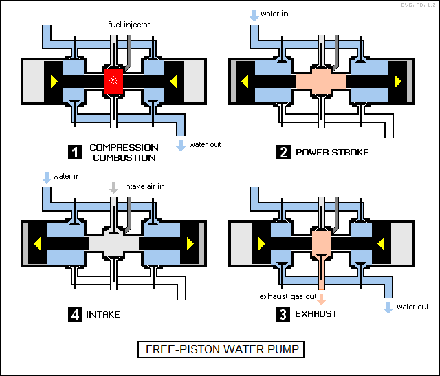
One configuration, the "free piston engine", is so unusual that it is worth adding here. The name is due to the fact that this class of engine doesn't have any driveshaft: the pistons just pop back and forth without a linkage to anything, being driven forward by combustion to compress a closed-off air space and being driven back again. This sounds pointless, but the motion of the pistons can be used directly to pump gases or liquids.
The diagram below shows a free piston engine used as a water pump. Its basic operation uses the four-stroke Diesel cycle; there is no reason in principle that it couldn't use a four-stroke Otto cycle or a two-stroke cycle instead. If a free piston engine were used to pump gases, say to drive a jackhammer, it could be made simpler, with the air pumped into the combustion chamber and the gas driven out the engine exhaust. The advantage of a free piston engine is obvious: it is much simpler and uses fewer parts than a comparable Diesel engine driving a separate pump.
* Another class of heat engine in common use is the "turbine" engine. The most common application of the turbine engine is in aircraft propulsion, in the form of "turbojet", "turbofan", and "turboshaft" engines, but it is also used to propel ships and to provide electrical power generation.
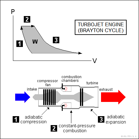
Turbine engines are generally known as "Brayton cycle" engines. A turbojet is an "open" Brayton cycle engine, in that it operates on a continuous flow basis rather than in a loop, as follows:
A turbojet is a little different from the other engines considered in this section because it is mainly intended to generate thrust. Turbine engines used to power ground vehicles or ships, "turboprop" engines used to spin an aircraft propeller, and "turboshaft" engines used to spin a helicopter rotor mainly generate torque.
"Closed" cycle turbine engines are used in powerplants and on large vessels. They may operate much like aircraft turboshafts, or they may be driven by compressed steam heated by an external thermal source. The steam then drives a turbine to provide power, and is finally cooled to be routed around to the intake of the compressor again. Closed cycle engines include secondary "heat exchangers" to draw some of the heat out of the exhaust of the turbine and preheat the input, improving energy efficiency.
* One elegantly simple example of an open-cycle turbine-based heat engine was a solar power plant proposed for the hot deserts of Australia. The design looked something like a big chimney, as tall as a skyscraper, that contained a set of turbines. The chimney was open at the bottom and was surrounded by a circular greenhouse-type structure in which the ceiling rises from the rim to the center. The sun heated up the air in the greenhouse; the hot air flowed inward and then into the openings in the bottom of the chimney, and rose up the chimney into the cooler air at the top, driving the turbines.
What was particularly interesting about this scheme from the point of view of elementary physics is that it illustrated how a temperature difference, in this case between the bottom and top of the chimney, was required to allow the engine to work. If it wasn't, the air at the bottom of the chimney would not rise and the turbines would stay idle. In addition, the greater the temperature difference -- the hotter the air at the bottom of the chimney compared to the air at the top -- the faster the airflow up the chimney, allowing more power to be obtained out of the turbines.
* Another interesting and unusual engine from a physics point of view is the "dipping bird" toy. This item consists of a bird with a glass body made of a tube with a head and beak on one end and a relatively large bulb on the other. The body pivots on a two-legged stand. The bulb is filled with a fluid that vaporizes easily at room temperature.

To get the dipping bird to work, a glass of water is set in front of it and its beak is placed in the water. The bird will pop upright and stay there for a while; then tip over, put its beak in the water, and remain there for a while; and will then pop upright again, repeating the cycle until the water supply goes dry. What happens is that, while the bird is upright, the volatile fluid in the bulb in the tail evaporates and rises to the head. This upsets the bird's center of gravity and it pivots over, dropping its beak into the water. The water cools the fluid and it flows back down to the bulb -- incidentally, the bird's body never goes horizontal or below horizontal. This shifts the center of gravity back and the bird goes upright again.
The dipping bird obtains its energy from ambient heat, but it needs a cold sink, the glass of water, in order to work. Of course, the bird won't dip if the ambient temperature is too cool to allow the fluid to vaporize, and it won't right itself if the ambient temperature is too warm to allow the fluid to liquefy.
This is not a practical engine, though in the 1970s a humor magazine, reflecting the early energy conservation fad of the decade, envisioned giant dipping birds operating as central power stations, and even drew up blueprints. However, the same principle has been considered for practical applications. In the early 1990s, work was done on the development of torpedo-sized roving robot submarines for oceanographic studies. These machines -- sometimes called as "Slocums" for Joshua Slocum, who in 1898 was the first person to sail around the world solo -- are powered solely by temperature differences in the oceans.
A Canadian engineer named Doug Webb came up with the idea for the powerplant. He had been working on a sea float that could control its flotation. The float contained an oil reservoir and an external bladder: the oil was pumped out of the float into the bladder to make the thing rise, and pumped back in to make it sink. This was a simple enough idea, but Webb kept thinking it over and coming up with refinements. First, he decided that he might not really need to use a pump, he could just shift oil around by heating and cooling it. Next, he realized that the temperature differences at different depths in the ocean could do the heating and cooling for him. Finally, he realized that if he put "wings" on the float, it would be able to control its direction as it sank or rose.
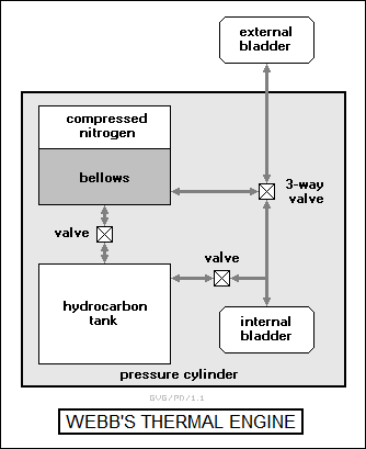
The thermal engine that Webb finally came up with hardly looked like an engine at all. The engine components were contained inside a cylindrical pressure casing that made up a body section of the Slocum, except for an inflatable bladder mounted outside the cylinder in the Slocum's frame. The bladder could be filled with liquid glycol (normally used as automotive antifreeze) and was connected to a matching one inside the cylinder through a tube. The cylinder also contained a pair of pressure tanks, one containing nitrogen and a bellows filled with liquid glycol, and the other containing a special pure hydrocarbon. The components were linked by a system of valves, as shown below:
The scheme for operation of this device was devious. The hydrocarbon was liquid at about 15 degrees Celsius and solid at about 5 degrees Celsius, with the transition between the two at about 10 degrees Celsius. Solidified, the hydrocarbon resembled candle wax.
On the surface, the external bladder would be filled with glycol; the internal bladder was empty; the hydrocarbon was liquid and the hydrocarbon tank was full; and the bellows was full of glycol. In this state, the Slocum floated. To make it sink, the 3-way valve was opened, causing the glycol to flow into the internal bladder.
At the bottom of the Slocum's descent, a kilometer and a half under the sea, the submarine was cold enough to cause the hydrocarbon to freeze. This caused it to shrink by 10%, with the evacuated space drawing off the glycol from the internal bladder through a valve. To ascend, the 3-way valve was closed to connect the bellows and the external bladder, and the compressed nitrogen then drove the glycol into the external bladder, causing the Slocum to rise. This done, the 3-way valve was closed again, and the valve between the bellows and the hydrocarbon tank opened. As the Slocum rose, the hydrocarbon expanded, forcing the glycol back into the bellows and compressing the nitrogen. By the time, the Slocum had reached the surface and was ready for another dive.
The engine could operate effectively under the pressures of the deep sea. No fuel was required, though the Slocum did need battery power to activate the valves. It wasn't a very powerful engine: in practice, it could propel a 40 kilogram Slocum no faster than a kilometer per hour. That was still fast enough to allow the Slocum to travel across the seas over a period of months or years. Since the Slocum was supposed to operate unattended for five years in a harsh oceanic environment, the diving fins were fixed at an angle for simplicity, with the Slocum adjusting its orientation by shifting the battery pack inside the pressure cylinder.
* Webb got his thermal engine to work, and development of Slocums has continued. A prototype named "Spray" was sent on a journey from Greenland to Spain in the spring of 2006, leading to mass production of Slocums; they are now in widespread use. It's certainly fun to see such a clever way of getting something for seemingly nothing.
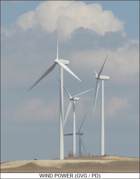
Many forms of renewable energy systems -- wind power and hydropower -- have a similar sort of appeal. Obviously, none of these machines actually violate the law of conservation of energy, they just make use of energy sources available in the ambient environment, with the energy inputs provided ultimately by the light and heat of the Sun. Trying to trace out the engine cycles for wind power (global weather) and hydropower (global rain cycle) would be an interesting exercise.
BACK_TO_TOP* A heat engine taps the flow of heat from a hot source to a cool sink to do work. It is also possible to reverse this flow, using work to remove heat from a cool source. This is the fundamental principle of how a refrigerator (or air conditioner) works.
In practice, a simple "refrigeration system" consists of a long sealed pipe arranged in a loop. Half of this loop is placed inside the refrigerator while the other half is placed in the environment outside the refrigerator, where the heat from the inside will be dumped. Both halves of the loop of pipe are turned back and forth with a series of hairpin turns to make them more compact, forming what are referred to as "coils", though they only coil in two dimensions, not three as in a coil spring.

The half of the loop inside the refrigerator is called the "evaporator coil" or just "evaporator", while the part outside the refrigerator is called the "condenser coil" or just "condenser". There are of course two connections between the evaporator and condenser. One connection is linked by an electric compressor, while the other is linked by a "flow restrictor" or "expansion valve".
The entire loop is filled with a "working fluid" or "cooling fluid" that changes easily from liquid to gas. The compressor drives the cooling fluid from the evaporator into the condenser, while the expansion valve throttles the flow of the cooling fluid from the condenser back into the evaporator. The cooling fluid evaporates as it goes from the condenser through the expansion valve into the evaporator, and becomes cooler due both to its change of state and its expansion in volume. The cool gas in the evaporator soaks up heat from inside the refrigerator. The gas is then condensed and liquefied when the compressor drives it from the evaporator back into the condenser. The warm fluid releases heat to the environment, and circulates back to the expansion valve to begin the cycle again. For more aggressive cooling, a "two-stage" refrigeration system can be used, consisting of two such refrigeration loops in cascade.
* In the earliest cooling systems, concentrated ammonia was used as the cooling fluid. It worked well from a thermodynamic point of view, but it had a major drawback: it was toxic. There are stories, apparently true, that people were actually killed by refrigerator leaks. This led to the introduction of a new class of cooling fluids, a set of compounds based on chlorine and fluorine known as "chlorinated fluorocarbons (CFC)". They looked like an absolutely perfect solution to the problem, since they not only had nearly ideal thermodynamic properties, but they were almost completely inert, non-toxic, and relatively cheap.
In the 1980s, however, atmospheric researchers began to discover that trace amounts of CFCs were accumulating in the upper atmosphere, where they were broken down by solar radiation. The chlorine in the molecules was able to cause the breakdown of "ozone", the O3 molecule, which covers the Earth in a high-altitude layer that is opaque to harmful radiation.
While ozone breakdown was only observed in the cold air above Antarctica, the possibility that increasing accumulations of CFCs could entirely wipe out the Earth's ozone layer -- destroying the shield that protects the planet from high-energy radiation -- was frightening enough to lead to international agreements to phase out the use of CFCs in refrigeration and air conditioning systems, as well as in their common use in plastic foam insulation. There is a popular misconception that CFCs were banned because they were toxic. Actually, the truth was that they were too inert for their own good. Once they were released into the environment, they didn't degrade until they floated to high altitudes where they could do the most harm.
CFCs were replaced by "hydrofluorocarbons (HFC)" that don't contain chlorine, and by "hydrochlorofluorocarbons (HCFC)" that do contain chlorine but break down before they reach high altitudes. Neither of these compounds were quite as efficient as cooling fluids or insulators as CFCs, however, so the conversion to HFCs and HCFCs was not straightforward. Worse, as it became apparent that human generation of "greenhouse gases" was leading to a gradual rise in global temperature, investigation showed that HFCs and HCFCs were extremely potent greenhouse gases. The focus is now on "hydrofluoro-olefins (HFO)", which are not greenhouse gases, though there is dispute that they are the right solution to the problem.
* An air conditioner works the same way as a refrigerator, pulling heat out of a room with the evaporator and dumping it into the outside environment with the condenser. If the flow of cooling fluid through the refrigerator was reversed, the system would then pull heat out of the environment and dump it into the room, heating the room. This is the basic principle of the "heat pump", a device in which the flow of cooling fluid can be reversed to either cool or heat a room. Heat pumps are efficient compared to most other forms of heating, but only in fairly moderate climates where the temperature changes are not too drastic.
* An even more interesting reversibility is that if a Stirling cycle engine is run "in reverse", with the device being driven instead of producing work, it makes a very nice cooling system. In fact, while the Stirling cycle engine remains something of an oddity long after its invention, the "Stirling cryocooler" is in increasing if somewhat specialized use as a compact refrigeration system.
The basic principle of the Stirling cryocooler is exactly the same as that of a more conventional refrigeration system: compress a working fluid in the external environment and allow it to cool to ambient temperature, then transfer the working fluid inside the refrigerator enclosure and allow it to expand as a gas. This is done with exactly the same four steps as the Stirling engine cycle, just implemented differently, with the "hot" cylinder becoming the "cold" cylinder, and the reverse:
As noted earlier, a warm object will emit infrared radiation. An infrared camera can obtain an image of an object just from its infrared radiation, even if there is no other light source available. The military is particularly fond of such infrared camera systems, which they call "forward looking infrared (FLIR)" imagers. The military also uses "heat-seeking" missiles, such as the well-known "Sidewinder" missile, with a "seeker" system will "home in" on a target aircraft from its thermal infrared radiation.
However, also as noted, both FLIRs and heat-seeking sensors suffer from an inherent constraint: they can't sense a target that is cooler than they are, and so it is desireable to cool the FLIR or heat-seeking sensor to improve its sensitivity. Early military FLIRs used in the 1960s had bulky refrigeration systems and had to be carried in fairly large aircraft. Early versions of the Sidewinder missile didn't have any cooling system, and so they could only be targeted on an aircraft's hot exhaust.
In the 1970s, improved versions of the Sidewinder were introduced with cooled infrared seekers. A seeker could be cooled with a can of compressed nitrogen gas with, the gas leaking out a pinhole to provide cooling; or by a "thermoelectric" cooler, which was a solid-state device that got cooler on one side and hotter on the other when an electric current was run through them. These improved "all aspect" Sidewinders could lock onto an aircraft target from any angle and no longer had to be targeted on an aircraft's exhaust. The use of compressed nitrogen meant that the seeker could only be cooled for a relatively short time, until the can of nitrogen ran dry; while thermoelectric coolers were inefficient, and took a relatively long time to cool off the missile. Better solutions were later introduced, the most significant in this context being relatively low-cost Stirling cryocoolers that could rapidly provide cooling for the seeker for as long as power is available.
BACK_TO_TOP* As a footnote, chemistry introduces complications into thermodynamic analysis, with the issue examined under the hybrid science of "thermochemistry". One aspect of thermochemistry, phase changes, has already been discussed. Chemical reactions add another level of complication.
The first relevant issue is that chemical reactions may be "exothermic" -- releasing heat energy -- or "endothermic" -- releasing it. It might seem that exothermic reactions should be spontaneous while endothermic reactions are not, but it's not that simple: some endothermic reactions are spontaneous. In addition, there are "reversible" reactions, that take place in both directions at the same time.
The first person to properly analyze the thermochemistry of reactions was an American physicist named Josiah Willard Gibbs (1839:1903), who published a series of papers on the subject in the late 1870s. What Gibbs realized was that a spontaneous chemical reaction was not just or even mainly dependent on the reaction releasing energy, it was also dependent on an increase in entropy. Gibbs devised a parameter known as "free energy" that was a function both of energy and entropy. Free energy is now more formally referred to in his honor as "Gibbs free energy" or just "G".
Gibbs was able to show in his work that if G increased in a chemical reaction, the reaction was spontaneous. Gibbs was painstakingly thorough and went much farther with the concept, showing how changes in concentration of a participant in a reaction could affect the free energy and so the rate of the reaction -- a fact that had already been known experimentally, being known as the "law of mass action". In Gibbs' terminology, changes in concentration of a participant changed the "chemical potential" of that substance, in a direct analogy to the potential energy of a mass in a gravitational field. Finally, Gibbs was able to incorporate phase changes -- from solid to liquid, liquid to gas, and so on -- into his concepts, with his "phase rule", allowing him to predict the results of chemical reactions under a wide range of conditions.
Gibbs' work also led to an understanding of "catalysis" -- the fact that adding, say, platinum powder to a chemical reaction could speed it up. That seemed suspiciously like a "free lunch", and figuring out how it fit into chemical thermodynamics was a puzzle. The Russo-German chemist Friedrich Wilhelm Ostwald (1853:1932), who did detailed research on catalysis, was an early European convert to Gibbs' ideas, translating Gibbs' papers on chemical thermodynamics into German in 1892, and giving considerable thought on how to fit catalysis into the system.
In an 1894 paper published in 1894, Ostwald suggested that catalysts could not change the nature of a reaction -- a reaction that wasn't spontaneous by itself wouldn't become spontaneous by the introduction of a catalyst -- but could speed up a reaction. He proposed that the catalyst bonded with one of the reactants, forming an intermediate compound that acted as a "template" where a second reactant could join with the first, releasing the catalyst to go through the cycle again. One common analogy of catalysis is of trying to write on a piece of paper without any surface to write on; it becomes much easier if a clipboard is available, though the clipboard really doesn't do anything to assist the writing process other than provide a "substrate".
The Swedish chemist Svante Arrhenius (1859:1927), one of chemistry's giants, suggested in 1889 that chemical reactions might need an "activation energy" to proceed -- just as a stone in a pit on top of a mountain needed to be pushed out of the pit before it could roll downhill. If this activation energy was low, its effect wouldn't be very noticeable, but if it was high, the reaction would not take place until, say, a certain temperature was reached -- and then it might take place abruptly. A mixture of hydrogen and oxygen gas seems innocent enough until the temperature reaches a certain level, and then the two gases combine explosively. Ostwald found this concept very handy in his considerations of catalysis, proposing that the complex formed between a catalyst and the reactants lowered the activation energy required for the reaction.
Arrhenius performed other studies in thermochemistry, most notably in the equilibrium of the dissociation and association of ions. However, further elaboration on thermochemistry becomes more of an exercise in chemistry than in thermodynamics, and so drifts outside of the range of this document. That's why this topic is discussed here as a footnote, to provide a lead to further study for those interested.
* As another footnote, the modern study of thermodynamics falls into the domain of "classical physics", which examines the behavior of the Universe at the "macroscale" level. From the early 20th, physics began to investigate the behavior of the Universe in the "microscale", the level of fundamental particles. As it turned out, the rules of the macroscale Universe don't necessarily apply to the microscale Universe -- the most notable example being "wave-particle duality", in which basic particles have characteristics of both waves and particles, but not both at the same time. There was also the reality that, at the atomic level, changes in energy were not continuous but discrete or "quantized".
The field of "quantum" physics arose to account for the strange behavior of the Universe in the microscale. It didn't really overthrow classical physics, since of course, the puzzling behavior of individual particles adds up to the long-established behavior of large collections of particles -- in somewhat the same way that a video image consists of an array of individual color dots or "pixels" that add up to an overall image. This reality is known as the "correspondence principle".
Thermodynamics focuses on the macroscale and so remains solidly rooted in classical mechanics, but from the 1990s, a faction of researchers emerged who were interested in seeing if the laws of quantum physics could provide insights in the field. The early work tended towards the confused -- for example, some claiming that at the quantum level, the SLOT didn't hold any longer, meaning that perpetual-motion machines could be possible. Others suggested there would be no change from classical thermodynamics at the quantum level.
Actually, it's obvious, by putting the correspondence principle in reverse, that macroscale thermodynamics doesn't apply at the quantum level. If quantities like temperature are defined through the statistics of large assemblies of particles, then the statistics are increasingly off base as an assembly gets smaller. In the quantum limit of a single particle, the concept of classical temperature makes no sense.
Indeed, early research showed that, at the level of assemblies of a few dozen atoms, measurements gave results that didn't match what was expected by macroscale thermodynamics. Further work showed that at the quantum level, the laws of thermodynamics didn't go away -- instead, they became more complicated, for example with a range of variations in the SLOT, depending on the quantum system. The work did suggest that, if the laws of macroscale thermodynamics aren't overthrown at the quantum level, there still may be some wiggle room in the microscale.
For now, the work is largely theoretical, but researchers involved see possibilities for applications, such as improved lab refrigeration systems. It may or may not amount to anything practical; research continues.
BACK_TO_TOP* This document began life as a component in a survey of classical physics, the first version being released in 1999. In 2018, I decided to break into three parts, including documents on classical mechanics, waves and optics, and this document on thermophysics -- which was given a revcode of v1.0.0.
* Sources include:
I browsed through the Microsoft ENCARTA interactive encyclopedia to provide many of the additional details included in the v2.2.0 version. I used Web searches as well; the Wikipedia online encyclopedia was very useful, but in general I just picked up bits and pieces from here and there and fitted them together.
* Revision history:
   v1.0.0 / 01 jul 18 / Broke out from general classical physics document.
   v1.0.1 / 01 may 20 / Review & polish.
   v2.0.0 / 01 jul 22 / Rearranged, discussions of chemical & quantum aspects.
   v2.0.1 / 01 jun 24 / Some rewriting on chemical thermodynamics.
BACK_TO_TOP