
* A knowledge of the behavior of light has led to the development of technologies to correct eyesight, using "eyeglasses"; provide close-ups of the very small, using a "microscope"; observe the very distant, using a "telescope"; and manipulate light and images in a wide range of other ways. This chapter provides a survey of modern optical technology.
* The basis of optical technologies is the bending of light rays. Any object that is generating or reflecting light can be thought of as a source of an infinite set of light rays; each point or element of the object generates its own infinite set of rays in all directions from which it can be seen, with a single ray linking the element to a particular viewer. This sounds exotic, but it's simple: all it's saying is that an element of an object can be viewed from any angle, with a simple straight line path that light can follow between the element and the viewer for each angle.
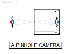
The best way to see this is to understand the simplest optical device, the "pinhole camera" or "camera obscura". Suppose Dexter builds a big cube that light can't get into, so he's completely in the dark when he crawls inside. However, he builds a box into one wall of the cube, with a pinhole on the front of the box to let light in, and a translucent screen on the rear of the box so he can see the light falling in through the pinhole. Somewhat surprisingly, the screen displays an upside-down view of the world as seen beyond the pinhole.
Consider a simple visual target, consisting of four different-colored diamonds clustered side by side, set up beyond the pinhole, and for simplicity consider only the ray of light coming from the precise center of each diamond. Although there are rays of light running from the center of the four diamonds in all directions from which the diamonds are visible, there's only one ray from the center of each diamond to the pinhole. These four rays pass through the pinhole and fall on the translucent screen at the back of the pinhole camera; of course the ray from the bottom diamond falls on the top of the screen, the ray from the top diamond falls on the bottom, the ray from the left diamond falls on the right, and the ray from the right diamond falls on the left. The sum of the rays from the diamonds create an upside-down image of the target on the screen.
The image of the target will get bigger if Dexter moves the screen back from the pinhole, but that image will also get fuzzier and in particular fainter. That pinhole can only admit a small amount of light, and the bigger the image, the larger the area that the light is spread over. Making the pinhole bigger will result in a brighter image, but also a fuzzier one, since the larger pinhole can be considered as like a set of adjoined small pinholes that are slightly offset from each other, resulting in a matching set of superimposed images that are slightly offset from each other as well. A pinhole camera is an interesting toy, but it's not generally all that useful.
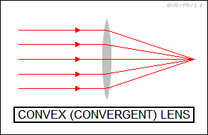
* To build more interesting optical devices, Dexter needs to use lenses or mirrors. He starts out with lenses, coming up with a "magnifying glass", one of the oldest useful optical technologies. It is simply a "convex" lens, a disk of glass thick in the middle and thin at the edges, with the curvature of the lens matching the curve of a shallow parabola.
The magnifying power of a single convex lens is related to its "focal length". Suppose rays of light are sent through a convex lens directly face-on to the lens, entering the front of the lens in parallel and then emerging from the back bent at angles that converge on a single location behind the lens, the "focal point". If Dexter wants to use a magnifying glass to start a fire from sunlight, he moves the glass until the focal point sits on the item to be ignited. This concentrates all the rays of light passing through the lens onto a single point, providing enough focused energy to start a fire.
The distance to the focal point from the back of the lens is the focal length. The focal length decreases as the curvature of the lens and the refractive index of the lens material increase. A parabolic curvature is required to bring rays entering the lens to a single focus; if the lens curvature were a section of a sphere instead, rays from the outer edges of the lens would come together at a closer focus than rays near the center, a defect which is known as "spherical aberration".
Even if the lens is properly ground, since the index of refraction is wavelength dependent, light of different colors will come to different focal points, with red light coming to a different focus than blue light. This error is called "chromatic aberration".
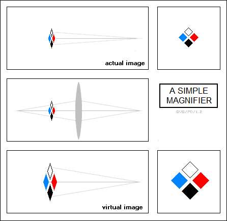
* The magnifying power of a single convex lens increases as the focal length of the lens decreases, by the simple fact that this increases the viewing angle of the target to the eye. Let's go back to the simple visual target, consisting of four colored diamonds. If Dexter holds it up to his eye, from a certain distance the target has a certain angular size in degrees, with the rays of light from that target covering that range of angles. If he moves the target closer, its angular size increases; if he moves it away, its angular size becomes smaller.
Now he places a simple convex lens between the eye and the target. With the lens in the way, the shortest optical paths to the four diamonds are no longer simple straight lines. The lens acts to bend or reroute rays that wouldn't have reached the eye in direct vision, giving a modified view of the target. A shorter focal length results in a greater "leverage" of the image size, resulting in an image with a larger angular size.
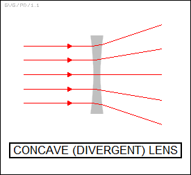
Lenses can also be built in a "concave" format, thick at the edges and thin in the middle. Rays passing through a concave lens will diverge, not converge, as they pass through the lens; this will result in a smaller image. In addition, there is no reason why a lens can't be built in a "convex-concave" format -- convex on one side, concave on the other, with the light rays converging on the convex side and diverging on the concave side. The usefulness of these two lens configurations is less obvious, but they will come up later.
* The human eye is a classic example of a single-lens "device", of course well predating any human-built optical technology such as magnifying glasses. The eye is in fact so sophisticated that there are those who proclaim it as an example of "intelligent design" behind the natural world. It seems too elaborate to have ever been constructed by the "screening and selection of random natural changes" described by evolutionary science.
The human eye is a fluid-filled sphere with a convex lens that focuses light on the matrix of rods and cones, discussed earlier, covering the retina on the back inner surface of the eye. The lens is protected by a transparent sheath named the "cornea" and a layer of fluid; the lens is also partly covered by a "shutter" called the "iris". The iris opens wide in the dark to admit more light into the eye through the central "pupil", and narrows in bright light to keep the retina from being overloaded with light, or "overexposed". A set of muscles point the eye in the desired direction; another set changes the curvature of the lens to adjust its focal length to focus on near or far objects; while a third set adjusts the iris to deal with changing light conditions.
The eye in itself only receives images; also as mentioned earlier, the nervous system network behind the eye and the optical interpretation sections of the brain do a great deal of "processing" on the images that gives our visual sense a number of quirks. Further discussion of the processing of images is outside the scope of this document, but it is worthwhile to realize that our "picture" of the outside world is by no means a crisp photograph.
* It is also worthwhile to realize that not all animals have an eye like that described here. Cats and owls, which generally hunt at night, have eyes that do generally conform to this description but don't have cones, compensating with more rod cells to give more detail. Of course, insects have complicated multifaceted compound eyes very much unlike those of humans.
Defenders of evolutionary science counter the "intelligent design" claim by pointing out the range of forms of the eye. Some microorganisms have primitive optical sensors that can hardly be called eyes, implying an evolution of capability to more capable schemes; the widely varying forms of eyes, such as the compound eyes of insects versus those of humans, suggest an evolution through history to different structures that do much the same job; and the variation in detail of eye function between related species, such as humans versus cats, suggest an evolutionary process of adaptation of similar structures to different lifestyles.
* This is getting off the subject of physics, but it does lead back to the main stream of the discussion, since another counter to the "intelligent design" claim is that the design of the eye isn't intelligent in all respects: few humans have "perfect" vision. It would be nice if we were born with the ability to adjust our eyes to correct for deficiencies, but we can't, so we resort to the technological fix.
One of the earliest applications of optical technology was a tool for correcting flawed vision: "spectacles" or "eyeglasses". Eyeglasses are without question the most important and widespread example of optical technology, and they have been for a long time. The first glass lenses appeared in Europe in the 13th century. Not only was the new technology quickly put to use in magnifying glasses, but some bright person quickly got the idea of mounting two lenses in a wire frame that could be propped on the nose and around the ears to provide corrections for defective vision. Eyeglasses were in common use by the time of the Reformation.
Eyeglasses are designed to compensate for defects in the lens of the human eye. A nearsighted eye can only focus on close objects; nearsightedness can be corrected by concave spherical lenses, essentially bringing the images of far objects closer. A farsighted eye can only focus on far objects; farsightedness can be corrected by convex spherical lenses, essentially pushing the images of near objects away.
Eyeglasses can also be made as "bifocals", with an upper lens segment to focus on distant objects and a lower lens segment to focus on near objects. The invention of bifocals is generally credited to the great American entrepreneur, scientist, inventor, and diplomat Benjamin Franklin (1706:1790), who came up with the idea in 1760. Bifocals led to "trifocals", with upper, middle, and lower segments to focus on far, intermediate, or near objects. In modern times, plastic "contact lenses" that can be placed on the eye have been developed as a replacement for simple eyeglasses.
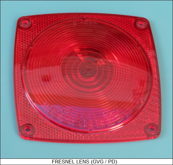
* Incidentally, although the optical technologies in this chapter generally use convex, concave, or convex-concave glass lenses, there is a wide range of alternative configurations for lenses. One of the most common is the "Fresnel lens", of course the invention of Augustin Fresnel. This is basically a short focal-length convex lens, which would normally be thick and heavy, that has been "flattened" by taking ring sections of the lens; trimming off the base of these rings; and then laying them down again concentrically in a flat plane. A Fresnel lens can't bring light to a tight focus, but it can concentrate light effectively enough, and it is used in lighthouse beacons, flashlight lenses, lenses for warning blinkers, concentrators for solar electric cells, and so on.
It is possible to build lenses based on diffractive instead of refractive principles. A "Fresnel zone plate", another one of Fresnel's inventions, consists of an opaque disk into which concentric rings have been cut, with the rings arranged to produce the proper diffractive focus. Fresnel zone plates are useful for focusing light in a system built on a stamped-metal chassis, saving the cost of a separate component, or in micro-sized systems where building and placing a glass or plastic lens would be difficult,
In addition, it is possible to build glass or plastic lenses on diffractive principles, in the form of "binary optics", in which the lens looks like a set of successively smaller disks stacked on top of each other. Binary optics also works well for constructing miniaturized lenses.
BACK_TO_TOP* A simple magnifying glass can provide enlargements of up to about 15 times. The problem is that, since a single lens magnifies by bending light rays into a shorter and shorter focus, the focus eventually becomes too short to be usable. The solution is to use a second lens to perform another level of bending.
Such a "compound microscope", as opposed to the "simple microscope" or magnifying glass, uses two convex lenses mounted in a tube. The lens at the front, known as the "objective" lens, has a very steep, short focal length, giving it large magnifications of nearby objects, while the lens at the back, known as the "eyepiece", has a longer focal length, allowing it to bring the image provided by the objective lens back into a useful focus, as well as providing another factor of magnification. A compound microscope can provide magnifications of up to 2,000 times.
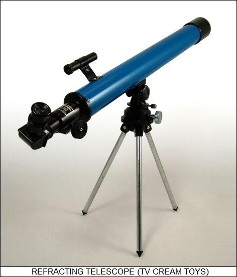
* Much the same concept, using an objective lens with a longer focal length mounted in a tube with an eyepiece lens, can be used to build a "telescope" to observe distant objects. Such simple "refracting telescopes" or "refractors" were introduced early in the 17th century, with Galileo being the most notable of the pioneers.
Chromatic aberration was a real problem for refractors for about two centuries, since it created a colored halo around objects. Telescope builders finally realized that chromatic aberration could be minimized by using a lens that was convex on both sides and made of a glass with a high index of refraction, mated to a lens that was concave on one side and convex on the other and made of a glass with a much lower index of refraction. The action of two lenses canceled out the chromatic aberration.
A common misconception about astronomical telescopes is that their main function is to provide magnification of distant objects. That is not really the case. The interference of the continuous rippling optical variations in the atmosphere means that a really big telescope here on Earth can't get any more of a detailed image of a celestial object than a moderate-sized telescope can. This is known as the "seeing" problem; the "seeing" is better from some sites, usually on mountaintops, than it is on others, but it never goes away.
However, cosmic objects may be very large but very faint. For example, the Andromeda Galaxy, the nearest major galaxy to our own, has an apparent size in the sky seven times that of the full Moon, but is so far away and faint that only the brightest portion of its central "nucleus" can be seen with the naked eye, and then only on a dark night. That means light collection is actually more important than magnification.
The light collecting ability of a telescope is a function of the telescope's "aperture", or total amount of light collecting area, which for a refractor is the area of the objective lens. Magnification is simply a function of the eyepiece. Since the area of a disk is proportional to the square of the diameter of a disk, doubling the linear dimensions of an objective lens quadruples the area and light-gathering capability. A refractor with a 20-centimeter objective lens has four times the light-gathering capability of a similar instrument with a 10-centimeter lens.
From the beginning of telescopic astronomy, astronomers have sought bigger apertures. Bigger and bigger refractors were built, leading to the Yerkes refractor, which went online in 1897 and had an objective lens a bit over a meter in diameter. Nobody ever built a bigger refractor. Larger lenses were just too hard to grind, and it was difficult to fabricate thick, clear glass; worst of all, a huge lens tends to warp under its own weight. Modern large telescopes are "reflectors", using mirrors, discussed later. However, refractors still remain in widespread use in small telescopes and binoculars.
* One interesting variation on the refracting telescope is the door peephole, which allows a homeowner to see who's standing outside at the door. Such a peephole consists of a "fisheye" lens and a convex eyepiece lens. The fisheye lens has an exaggerated curvature on the outer side that bends light rays inward over a very wide field of view. Since that by itself would result in an impractically short focal length, the inner side is concave to bend the accumulated light rays outward again and focus them on the eyepiece lens so they can be viewed.
* One of the most common optical technologies, aside from eyeglasses, is the camera. Cameras in general consist of a lens system focusing an image on plastic film coated with photosensitive dyes, or in modern times, an electronic imaging sensor array that produces a "digital" image. Both films and imaging sensors are complicated subjects by themselves; they are generally ignored here to focus on camera optics.
The camera was invented in the 19th century. 19th century cameras originally used photographic plates instead of flexible film, with the plate made of glass covered with photosensitive dyes. A film plate could be placed inside a pinhole camera to obtain an image, but it was very difficult to obtain a good image with such crude technology.
The first really practical cameras used a convex lens to focus light on a film plate, with an angled, partly transparent mirror in the optical path to reflect the image to a ground-glass plate that acted as a "viewfinder". The light from the lens was "gated" by a shutter system. The photographer could hold the shutter open longer in faint light to get a good image, though the longer the shutter time, the harder it was to keep the image from being blurred due to motion during the "exposure". The lens of the camera was fitted on a "bellows" system that could be moved back and forth to adjust focus.
Late in the 19th century, the Kodak company introduced the simple portable "box camera", which had a fixed shutter speed and a fixed focus, allowing it to take adequate pictures of objects a few steps away in normal lighting conditions. The box camera, crude as it was, eliminated the monopoly of the professional cameraman on photography, allowing everyone to take pictures. Cheap film cameras evolved from there, one particular innovation being film on a plastic roll -- a technology introduced in the 1920s that became all but standard until the intrusion of non-film digital electronic cameras in the 1990s, which quickly reduced film cameras to a niche product.
A typical reasonable-quality modern digital electronic camera will feature:
Midrange or high-end cameras can use special lens assemblies, such as a heavily curved fisheye lens for wide-angle shots, that can be fitted over the regular camera lens assembly. Such modern "point and shoot" allow amateurs with modest experience to often take professional-quality images, though of course the professionals can obtain them much more regularly and under more difficult "shooting" conditions.
BACK_TO_TOP* The examples in this section so far have used lenses. Very similar principles apply to mirrors, though of course with mirrors the rays are reflected, not passed through.
The most familiar mirror is the flat bathroom mirror; rays bounce directly off of it. When Dexter looks into a bathroom mirror from a given distance away, the image of his face seems to be at an equal distance on the other side of the mirror. This is handy for brushing his hair and the like.
Flat mirrors can be arranged in a tube at oblique angles to see around corners. Such a device is known as a "periscope". Periscopes are of course familiar from their use in armored vehicles and particularly submarines. A classic submarine periscope features an evacuated tube and, since the tube tends to be long, telescopic elements. In modern times, submarine periscopes may actually carry electronic imagers, with the images relayed back to the submarine over wires.
Periscopic principles are also used in the "coude focus" for telescopes, which is a periscopic system that can rotate as the telescope tracks the sky to bounce the image onto a camera system, a spectroscope, or other instrument. In addition, simple telescopes use mirrored prisms to create "folded optics", reducing length; the best known example is the ordinary binocular, in which the mirrored prisms bounce the dual images obtained from the separated objective lenses to the closely-separated eyepieces.
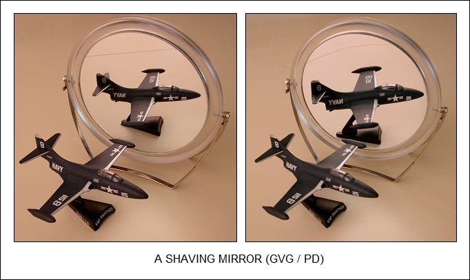
* Mirrors can also have concave or convex surfaces. Common handheld "shaving mirrors" will have a flat mirror on one side and a concave mirror on the other; the concave surface will move the focus towards the surface of the mirror, with this "leveraging" providing magnification. When Dexter looks into the concave mirror, the image of his face appears to be closer on the far side of the mirror.
In contrast, the fisheye mirrors sometimes used on the side rear-view mirrors of trucks and the like are convex, extending the focus to allow a wider field of view at the expense of some reduction in the size of the image. If Dexter looks into a convex mirror, the image of his face appears to be farther away on the far side of the mirror. Fans of Gary Larson's FAR SIDE will remember the cartoon in which a woman driver sees a huge eye filling up her side rear-view mirror, which is marked with the text: OBJECTS ARE NEARER THAN THEY APPEAR.
One of the advantages of mirrors is that all wavelengths of visible light reflect in the same way, and so chromatic aberration doesn't occur. In Newton's day, the compound lens system used to cancel chromatic aberration hadn't been invented. Since Newton didn't realize that different materials have different indexes of refraction, he didn't think there was any way to get rid of chromatic aberration in a refracting telescope, and so he invented a "reflective" telescope or "reflector" with a concave mirror at the bottom to collect and focus light.
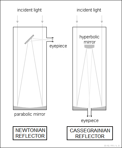
Newton's form of reflector became known, of course, as "Newtonian"; this form involves reflecting the light from the main "primary" mirror to a small "secondary" mirror mounted in the front end of the telescope, with the secondary mirror set at an angle to reflect the image to an eyepiece on the side. The main alternate form in modern times is "Cassegrain" telescope, in which a secondary mirror with a hyperbolic surface reflects the light back down through a hole in the primary mirror into an eyepiece.
Difficulties in making mirrors that could keep their form and remain shiny made reflectors inconvenient until late in the 19th century, when techniques were discovered for laying down a thin layer of silver on a glass mirror. In the next century, improved techniques were developed where aluminum was laid down on a mirror blank as a hot metal vapor in a vacuum chamber. Since it is very difficult to build very large lenses, reflectors are now the norm for large telescopes, with apertures far larger than any refractor ever built.
* One of the problems with a standard reflecting telescope is that its field of view is fairly narrow; the parabolic curvature of the mirror elongates the part of the image at the edges of the field of view, a phenomenon known as "coma". Wide-field telescopes generally use a "hybrid" reflector-refractor configuration known as a "Schmidt telescope".
The Schmidt features a primary mirror with a spherical curvature, which would normally give spherical aberration, but the front of the telescope is fitted with a "corrector" lens -- thick on the edge, thick in the center, thin in between -- to adjust for spherical aberration. The "Schmidt-Cassegrain" configuration, with a hole in the primary mirror and the eyepiece in back, is a popular design for compact amateur telescopes.
* Through most of the 20th century, most large astronomical telescopes recorded their images on photographic film. This not only allowed recording the images, permitting inspection at leisure and long-term archiving, but the photographic film could build up faint images over long exposures. Modern large astronomical telescopes now use electronic sensor systems, linked to computers that store and analyze the image data. Modern sensors and computer power have been able to compensate for the "seeing" problem to an extent, allowing large telescopes to obtain more detail.
Telescopes carried on orbiting astronomical satellites, such as the famous NASA Hubble Space Telescope, may have a "turntable" that carries different sensors, for example one with a wide field of view and coarse angular resolution, another with a narrow field of view and high angular resolution, and a third that performs spectroscopy. Other switching schemes may be used to divert a space telescope's image if the sensors are too large to be mounted on a turntable.
* It is difficult to grind the large mirrors for big astronomical telescopes, and traditionally they have had to be made out of glasses that have a low coefficient of thermal expansion, such as Pyrex and in particular a glass known as "Zerodur", since otherwise their precision surfaces would shift in shape with temperature, distorting their images. Large telescopes usually need a period to cool down at night before they can perform observations.
In fact, after the construction of the 5.1-meter Hale telescope at Mount Palomar observatory in the late 1940s, there was a general belief that telescopes couldn't get much bigger, because the thermal mass of the mirror would become so great that the mirror wouldn't be able to cool down and stabilize until the night was over. The mirror would also be impractically heavy to mount and use.
However, in the 1980s and 1990s new telescopes were designed that got around this limitation. New lightweight mirror materials, along with improved design and fabrication methods, mean that it is now practical to build mirrors up to eight meters in diameter. Even larger telescopes can now be made as assemblies of mirrors. The famous pair of Keck telescopes on Mauna Kea in Hawaii each use a set of 36 hexagonal thin mirror segments that are fitted together on a mechanical support structure. The support structure continuously adjusts the positions of the segments to ensure a good focus, with the adjustments controlled by optical sensors.
Each Keck telescope has a composite aperture of 10.1 meters, with four times the light-gathering power of the Hale telescope. This is by no means the end of the line, either; European astronomers are working towards construction of a 39.3-meter reflecting telescope using mosaic mirror technology. They originally wanted a 100-meter telescope, but though it was judged feasible the expense was too great.
Research is now being conducted on space telescopes, based on arrays of flat lenses that achieve focus through a diffraction grid fabricated in them. Such telescopes can have large effective apertures while being very lightweight, an important consideration for spacecraft since it is expensive to put payloads into orbit. It is unlikely that they will have much use on Earth, since their figures would be affected by air movements.
BACK_TO_TOP* Optical telescopes have led to telescopes to examine other regions of the spectrum. A typical radio telescope focuses long-wavelength radio signals using a large dish. The dish does not have to be as precisely built since the mirror of an optical telescope because the surface precision required increases as the wavelength of the electromagnetic radiation decreases, and radio wavelengths are very long compared to visible light wavelengths.
Infrared telescopes use more or less conventional optical telescope designs. However, infrared radiation is mostly absorbed by the atmosphere, and so ground-based infrared telescopes are only operated from very dry, high-altitude sites. To get around atmospheric absorption completely, infrared telescopes are often flown in balloons, high-flying aircraft, or as orbital satellites. They have to be cooled, traditionally with liquid helium in a double-dewar flask, to be sensitive to faint sources of radiation.
Short-wavelength high ultraviolet and X-ray radiation are also mostly absorbed by the atmosphere and have to be observed by satellites. These short wavelengths cannot be focused by a conventional mirror, since they are so energetic that they go right into it. However, they will "skip" over a mirror at low angles, like a flat rock skipping over the surface of water, and so they can be focused by "grazing incidence" mirrors, which look like tubes that taper to a smaller diameter in a smooth curve from front to back.
Such grazing-incidence mirrors are nested to increase the amount of radiation they focus. Typically, they consist of a primary stage with four nested cylinders with a parabolic curvature, feeding a secondary stage with four nested cylinders with hyperbolic curvature. The secondary stage focuses the radiation on an electronic detector array, which has to be shielded with lead along its bottom and sides to prevent stray X-rays from introducing noise.
The problem with the grazing incidence scheme is that the skipping angle gets shallower and shallower as the wavelength of the X-rays increases and the X rays become more energetic, resulting in a very long telescope. Another scheme, known as a "coded mask" telescope, is used for short-wavelength X rays. A coded mask X-ray telescope is essentially a pinhole camera, with a heavy metal plate perforated with holes mounted above a detector array. Multiple holes are used to increase the flux of X-rays to the detector array; the holes are carefully arranged so that the actual X-ray image can be sorted out with a bit of computer power.
A coded mask telescope can also focus low-energy gamma rays, but even it will not handle high energy gamma rays. They must be measured by "particle detector" systems that are way beyond the scope of this document.
* Since the 1960s, radio telescopes have been linked together to form radio interferometers that can compare the phase of radio waves from distant cosmic objects, providing very high resolutions. The resolution of a radio interferometer array is proportional to the spacing or "baselines" of the radio telescopes that make up the array. Radio telescopes have been linked up over continents to provide extreme resolution. Notice that the length of the baselines in the array only affects the resolution of the images obtained. The sensitivity of the array, or essentially the amount of radio energy it can collect, remains proportional to the sum of the areas of the individual radio telescopes in the array.
In the late 1980s, optical interferometer telescope arrays have been built as well. Due to the fact that optical wavelengths are much shorter than radio wavelengths, an optical interferometer requires extremely precise spacing and separations of present systems are no more than a few hundred meters.
BACK_TO_TOP* One of the interesting and amusing examples of optical technology is stereo imaging. Humans and most other primates, like monkeys and apes, have stereo vision; their eyes are set side-by-side in the face, with both eyes covering the same view but at a slightly different angle. The brain's visual processing system combines the two views to give information on the distance of objects. Animals, such as horses and many species of fish, that have eyes more to the side of the head have a wider field of view but only a limited stereo capability, directly ahead.
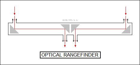
Old-style optical rangefinders, used on warships to find the range for naval guns, were based on exaggerating stereo vision. Such an optical rangefinder was essentially two telescopic periscopes with the objective lenses spaced widely apart, left to right. To estimate range, a sailor looked through the two eyepieces and adjusted a knob to bring the left and right views of the target together. Turning the knob also changed a range reading corresponding to the relative angle of the two objective lenses. Matching up the two images then gave the range to the target.
The basic idea behind stereo imaging is somewhat reversed from that of an optical rangefinder. The trick is to create two or more images of the same object, observed with an offset, and pass them to each eye in a superimposed fashion, with the brain's optical system merging them and producing an impression of depth. The crudest way to do this is to simply print the offset images side by side, and then provide registration marks so that readers can cross their eyes appropriately and get the proper stereo effect.
This is an uncomfortable scheme, and it is much easier to use a viewer, with a lens for each eye that bends each image to each eye so the eyes don't have to be bent themselves. This is the approach used in the old-fashion stereo viewers used a century ago, and the later "ViewMaster" equivalent. An acquaintance of mine made his own stereo images by taking a picture of, say, a building, then stepping several paces to one side and taking another picture of the building. He then pasted the prints onto cardboard to display using an old-time stereo viewer.
This technology has serious, even deadly serious, applications as well. Earth surveillance satellites, both for civil and military surveillance purposes, sometimes carry stereo camera gear, with one camera taking a picture of a target before the satellite passes over it and a second camera taking a picture of the target after the satellite passes over it. The stereo images can be viewed through a stereo viewer to reveal details that might have gone unnoticed in a two-dimensional image. Incidentally, observation satellites are often launched in orbits that take them over the same site at the same time every day to ensure relatively consistent lighting conditions, allowing for example to notice the movement of objects by the changes in shadows from observation to observation.
The "lenticular" plastic stereo cards occasionally used as trinkets or promotional gimmicks don't require either crossing the eyes, or a viewer. They consist of a set of images cut into narrow slices and interleaved into a card, then overlaid with a plastic panel consisting of an array of lenses organized as long narrow vertical strips and with a half-circular cross-section. The lenses optically sort out one of the interleaved images, depending on viewing angle, with an offset image sent to each eye to produce the illusion of depth; rotate the card onto its side and the stereo effect goes away.
Of course, obtaining a good stereo image requires high quality printing and accurate registration with the lens sheet. Cheaper lenticular trinkets, which use rows of coarse plastic prisms, simply give a different image when shifted back and forth; for example, a kitschy old standard is to have a pretty girl who is fully dressed from one angle, but is wearing much less from another. Flat-panel computer displays are now available that use lenticular technology to provide a stereo image, with the computer software slicing up the image and interleaving it for display.
Another traditional stereo scheme is the "anaglyph", which consists of one offset image in red overprinted with the other in blue. Blue and red glasses are used to merge the images and get the stereo effect. This scheme was also used in the notoriously trashy 3D movies of the 1950s, but it had a major limitation: it could only be used with black-and-white videos. Modern color stereo movies, such as those popular at theme parks, project the two images using two polarizations at 90 degrees to each other, and the glasses used by the audience similarly have two polarized lenses with the plane of polarization also at right angles to each other.
BACK_TO_TOP* The astute reader will have some questions about the glib statements made to this point. For example, sound is a wave phenomenon, a transfer of mechanical energy through air or some other medium. But what is the medium through which light is transferred? It transfers through a vacuum that by definition contains absolutely nothing.
That was a puzzle to physicists before the 20th century, and it was one of the reasons that there was uncertainty as to whether light was a wave or particle until Thomas Young's two-slit experiment seemingly settled matters in favor of waves. A wave implies a transmission medium, while a particle flies across empty space just fine. Since nobody could actually detect any medium that could propagate light waves, physicists had to imagine an invisible "luminiferous (light-bearing) ether" that permeated the Universe to do this job, but this was such an arbitrary construct that many were uncomfortable with it. It also led to another troublesome issue: if there was such an "ether" filling the Universe, how would the motion of the Earth, or any other object, affect the perceived velocity of light?
The great German-American physicist Albert Einstein (1879:1955) went a bit further and wondered if it were possible that the Earth or some other object might actually travel through the ether so fast that it would exceed the speed of light. Under such circumstances, a person would not be able to see his or her reflection in a mirror. Einstein moved from this line of reasoning to create his "Theory of Special Relativity", the first of the two major revolutions in physics in the 20th century. This theory postulated that there was no ether, and that the speed of light was always the same to all observers, no matter what their speeds relative to each other might be. This led to some very non-intuitive consequences.
* The fact that there was no ether also tended to undermine the wave theory of light. This was baffling, since light clearly seemed to exhibit wave properties, such as interference. There were other difficulties as well. For example, if a thermal emitter produced light of wavelengths all up the EM spectrum, the energy would have been infinite, destroying the Universe in the flare of a single match. Instead, a thermal emitter produces a black body spectrum, with the energy falling off above the peak emission wavelengths.
Another issue was the nice neat spectral lines of light emitted or absorbed by atoms. It seemed like atoms were some sort of resonant chambers for light, but nobody could figure out exactly why that would be so. Yet another puzzle was light polarization. As mentioned, if we put two polarized lenses in series and at right angles to each other, all the light is blocked out; but if we put another polarized lens between the two at a 45-degree angle, light will be attenuated but still filter through. There was no way to explain this in classical physics.
These and other puzzles led to the second major revolution in 20th century physics, known as "quantum physics". Quantum physics led to even more bizarre quandaries than relativistic physics, proclaiming that particles could be waves, waves could be particles, and that there were fundamental limits on how well physical interactions could be measured. Both relativistic and quantum physics broke the boundaries of conventional physics, and as such they leave the domain of this document. Relativistic and quantum physics are discussed in companion documents to this one.
BACK_TO_TOP* This document began life as a component in a survey of classical physics, the first version being released in 1999. In 2018, I decided to break into three parts, including documents on classical mechanics, thermophysics, and this document on waves and optics, -- which was given a revcode of v1.0.0.
* Sources include:
I browsed through the Microsoft ENCARTA interactive encyclopedia to provide many of the additional details included in the v2.2.0 version. I used Web searches as well; the Wikipedia online encyclopedia was very useful, but in general I just picked up bits and pieces from here and there and fitted them together.
* Revision history:
   v1.0.0 / 01 jul 18 / Broke out from general classical physics document.
   v1.0.1 / 01 may 20 / Review & polish.
   v1.0.2 / 01 jun 22 / Review & polish.
   v1.0.3 / 01 may 24 / Review & polish.
BACK_TO_TOP