
* While World War II led to the development of operational radar systems and the beginnings of electronic warfare, electronic technology also had an impact in radio navigation systems. This chapter discusses the navigation systems developed during the war, and also discusses some of their postwar descendants to provide a connection to the present.
* Allied researchers made considerable progress in the use of radio systems for air navigation during the war. However, the basic concept of using radio signals for navigation was not new: radio direction finding had been developed before the war and was used extensively during the war.
A "radio direction finder", also known as a "radio compass", used a loop antenna mounted on the back of an aircraft. If the plane of this antenna pointed to a radio beacon, the signal strength was a maximum, while a signal facing the loop induced voltages that canceled each other out, resulting in a weak or null signal. The loop antenna was connected to an amplifier, which drove an indicator on the cockpit's control panel.
"Automatic direction finding (ADF)" was an improvement on basic radio direction finding, which used a feedback control system to rotate the loop in such a way so that the signal was always a maximum. The control panel indicator then showed the direction of the antenna. A more sophisticated approach to ADF was to use two loop antennas, set up at a right angle to each other, and measure the ratio of the signals from each antenna to get the angle to the beacon.
Allied aircraft carriers also used a radio compass system designated "YE" (and the follow-on "YG") to guide fliers back home. The transmitter used a directional antenna to reduce the chance of an enemy locating the carrier with the signal. The YE signal for each carrier carried coded information to identify the carrier. Most ground-based radio beacons transmitted a two or three letter identifier in Morse code on their transmitter frequency to identify themselves, and it is plausible but unclear that YE/YG used the same approach.
In addition, Huff-Duff, the high-frequency direction finder system used to hunt U-boats, was used during the war as something like a radio compass in reverse. Pilots would call up Huff-Duff stations to get a bearing fix.
* A simple radio beacon could only give a pilot a line from the aircraft to the radio beacon, but could not provide such useful information as whether the aircraft was north or south, east or west of the beacon.
Radio beacons were often implemented with two loop antennas at right angles. Loop antennas operate directionally in transmission as well as reception, with one broadcasting a Morse code "A" and the other an "N". The two letters have complementary patterns, so a pilot would get a continuous tone when on the angle between the directions of the two antennas. The scheme was introduced by the German Lorenz company in the 1920s, licensed all over the world, and remained in service for decades.
Such a beacon could tell the pilot what "quadrant" the aircraft was in relative to the beacon, but it could not provide a true compass bearing, or "radial", to the beacon. The Germans did develop a radio beacon system named "Sonne (Sun)", or more fully "Elektra Sonne" in honor of Richard Strauss's opera ELEKTRA, that allowed determination of the radial. It was known as "Consol" to the Allies, and was so useful that it remained in service well after the war.
Consol was a radio beacon operating at 1 kilometer (300 kHz), with three fixed antennas in a row spaced a kilometer (one wavelength) apart. The antennas produced a complicated signal that allowed determination of the radial to the beacon. It performed a cycle of transmissions as follows:
If the aircraft was on a track roughly perpendicular to the beacon, the navigator could get a fix on it at two different locations along the flight path and use simple triangulation to determine the aircraft's position.
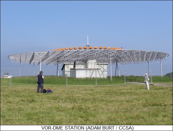
* The effectively universal postwar "VHF Omni-Range (VOR)" beacon system is similar to Consol in broad concept, except that VOR operates around 2.73 meters (110 MHz) and uses the phase difference between a continuous omnidirectional signal and a narrow beam signal, rotated using a phased array antenna, to give direction. The continuous VOR beacon signal is transmitted as a three-letter identification code in Morse.
When the aircraft is due north of the VOR beacon, the two signals are in phase; when the aircraft is due south, the two signals have reversed phase; with the phase difference varying between those two extremes. The Consol scheme was designed for use by a human navigator, while the VOR scheme was designed for use by an electronic box. VOR is strictly a line-of-sight scheme, and pilots have to navigate from station to station.
BACK_TO_TOP* Radio beacons were somewhat restricted in range, and more sophisticated radio navigation schemes were required for long-range navigation. As mentioned earlier, the Germans had developed a series of radio navigation systems, including Knickebein, X-Geraet, and Y-Geraet. These provided navigation beams, which were not only inflexible, but due to multi-path signal bounce and signal interference, could occasionally give drastically bogus results.
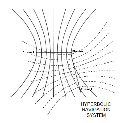
The British developed an entirely new scheme, known as "Gee" or "AMES Type 7000", that allowed an aircraft or ship to locate its position by timing the delays between two sets of signals. Gee used three transmitters, including one "master" and two "slaves", "A" and "B", that were sited about 80 to 160 kilometers (50 to 100 miles) from each other and transmitted on wavelengths in the range of 15 to 3.5 meters (20 to 85 MHz). The three transmitters sent out periodic radio signals in a four-part cycle, with each step of the cycle a millisecond apart:
The cycle repeats every 4 milliseconds, 250 times a second.
Ignore slave B for the moment, and focus on the initial pulse from the master and the response from slave A. A receiver on a bomber or other platform could determine the difference between the time of a master pulse and the responding slave pulse. By itself, all this can do is determine the difference in the distance from the bomber to the master station and the distance from the bomber to the slave A station. This difference in distance doesn't give enough information to locate the bomber. What it does is give the bomber's possible position as a curve overlaid on a map, with a different curve for each difference in distance to the two transmitters. A curve of constant difference between two separated points is known as a "hyperbola".
Now let's consider the double pulse from the master and the response from slave B. This also gives a difference in distance between master and slave, but since slave B isn't in the same position as slave A, the result is a position on a different set of hyperbolas. The navigator can identify the hyperbola based on the pulses from slave A, then identify the hyperbola based on the pulses of slave B, and determine the bomber's position from the intersection of the two curves.
Incidentally, an accurate determination of distance from a difference in timing required a precision timing source in the receiver gear on the bomber. Since this would have been expensive and troublesome to implement in a receiver for every bomber, the timing source in the receiver was designed to be slightly variable, and was synchronized to the pulses from the master station, which did have a precision timing source.
Gee was the ancestor of a number of such "hyperbolic" navigation systems. The name "Gee" was actually short for "Grid". Gee was a line-of-sight system, and its accuracy for bombing was poor. At a distance of 400 kilometers (250 miles), Gee could target a site within an ellipse about 1.6 kilometers long and 9.6 kilometers wide (1 by 6 miles).
* Gee was actually first proposed in 1937, but development didn't begin until 1940, when the TRE's Robert J. Dippy pitched the idea to A.P. Rowe. First tests were in August 1941, using a dozen handmade receiver sets fitted into Vickers Wellington bombers, with operational deployment planned for the following spring.
The scheme nearly came undone at the outset when one of the Wellingtons crashed onto enemy territory. Nobody really knew if the Gee equipment had survived the crash in recognizable shape, or if the Germans had taken notice of it if it had, but in the worst case the Germans could have a jamming system in place even before Gee was operational. The problem was dropped into the lap of R.V. Jones, who characteristically decided that the solution was trickery. He was enthusiastic about the job, which amounted to a prankster's paradise, "the culmination of all my prewar efforts in practical joking, with virtually as much of the national resources at my disposal as I wished."
First, he covered Gee's tracks. Gee stations were given additional masts so they would resemble Chain Home radar stations, and they were ordered to transmit unsynchronized pulses. Orders were given to ensure that even the name "Gee" was to be treated as top secret. The mounting racks installed in bombers to accommodate Gee receivers were given serial numbers appropriate to more conventional communications gear.
Jones then led the Germans astray, tricking them into thinking that the British were working on a new radio navigation system that was only a copy of the German Knickebein system. He felt that one advantage of this approach was that it would flatter the Germans, a useful ploy in any con game. He invented a fantasy Knickebein derivative named "Jay", and even defined imaginary transmitter sites.
Jones fed this information to German intelligence through an even bigger con game, the "Double Cross" system. British counterintelligence, helped by an alert public, swept up almost every agent the Germans sent to England, and gave them the choice of execution or becoming a double agent. Most became double agents, with a few becoming surprisingly enthusiastic for the Allied cause. The Double Cross agents fed German intelligence a steady stream of carefully controlled and subtly bogus intelligence.
Jones had one Double Cross agent send back a fake report of a conversation between two RAF officers that had been overheard in a hotel, with one officer complaining about how a superior had received credit for copying the German beam system, with the other replying that the "Jay beams" would still prove useful. Another fed back a report of how RAF bombers were being fitted with gear for the new "Jerry" radio navigation system. Using the term "Jerry" was particularly devious, since intelligence that seemed too consistent was suspicious, while still giving the hint that the name "Jay" meant "Jerry", providing a roundabout clue to the system's German origins.
Jones could not really know if his trickery worked until Gee was used in earnest. That finally happened in on the night of 8 March 1942, when 80 RAF Bomber Command pathfinders led a raid of 270 bombers against Essen, Germany, the opening blow in RAF Bomber Command's war on the German cities. The Gee transmitters in England provided navigation signals that covered the Netherlands and the Ruhr Valley industrial district in Germany. Jones expected that the Germans would get wise to Gee within three months, but it took them seven to even find out it existed. They weren't able to effectively jam Gee until early 1943, and after the war returning RAF airman who had been captured by the Germans during that time reported their interrogators had heavily questioned them about "Jay".
* An improved Gee receiver was developed that allowed the operator to switch between different frequencies and reduce the impact of jamming. Gee remained in service as a navigation aid in friendly airspace after it ceased to be useful for offensive purposes. It lingered on after the war, with the last Gee transmitter shut down in 1970.
The Germans began to make use of Gee after a time. In turn, the British made use of the German Elektra Sonne / Consol radio beacon system, choosing not to protest when the Spaniards allowed the Germans to set up a transmitter for the system in Spain, a clear violation of neutrality.
The Germans never built a hyperbolic navigation system. The Japanese did develop one that never got into service. The Japanese system was relatively crude, requiring the navigator to perform timing with a stopwatch as part of the procedure to determine the position of his aircraft or vessel.
BACK_TO_TOP* Gee was fine for finding one's way around, but didn't provide very good targeting accuracy. Precision targeting required something better, and to fill this need the British developed a navigation system named "Oboe" or "AMES Type 9000", which was used by Mosquito light bombers to identify targets in enemy territory for marking by large flares. Heavy bombers would then sight on the flares and plaster the target.
Oboe was based on radio transponder technology. The was to use two stations, each at a different and well-separated location in England, to transmit a signal to a Mosquito carrying a radio transponder. The transponder reflected the signals, which were then received by the two stations. The round-trip time of each signal gave the distance to the bomber.
Each Oboe station used the radio ranging to define a circle of specific radius, with the intersection of the two circles pinpointing the target. The Mosquito flew along the circumference of the circle defined by one station, known as the "Cat", and dropped its marking flares when it reached the intersection with the circle defined by another station, known as "Mouse". There was a network of Oboe stations littered over southern England, and any of the stations could be operated as a Cat or a Mouse as the need demanded.
The initial "Mark I" Oboe was derived from Chain Home Low technology, operating at 1.5 meters (200 MHz). The two stations emitted a series of pulses at a rate of about 133 times per second. The pulse width could be made short or long so that it was received by the aircraft as a Morse code dot or dash. The Cat station sent continuous dots if the aircraft was too close, and continuous dashes if the aircraft was too far.
Various Morse letters could also be sent, for example to notify the aircraft crew that the Mosquito was within a specific range of the target. The Mouse station sent five dots and a dash to indicate bomb release. The Mouse station included a bombsight computer, known as "Micestro", to determine the proper release time -- there being no particular logic in carrying the bombsight on the Mosquito when it was under the slavish control of the ground station.
* The basic idea of Oboe was dreamed up by Alec Reeves of Standard Telephones and Cables LTD, and implemented in a partnership with Frank Jones of the TRE. Oboe's first operational use was in December 1942, about the same time H2S was introduced. The Germans, observing the curved path of the Mosquito, called the system "Boomerang". The predictable path of the bomber was a vulnerability, compensated for by the fact that the speed and altitude of the Mosquito made it very hard to intercept. The major limitation of Oboe was that it was a line-of-sight system, useful for attacking the Ruhr industrial area but not targets deeper inside Germany.
Oboe was extremely accurate, with an error radius of about 110 meters (120 yards) at a range of 400 kilometers (250 miles), about as good as an optical bombsight. Late in the war Oboe was used for humanitarian purposes to perform food drops for the Dutch still trapped under German occupation. Drop points were prearranged with Dutch resistance contacts, with the food canisters dropped within about 30 meters (100 feet) of the aim point.
The Germans tried to jam 1.5 meter (200 MHz) Oboe signals, though by the time they did so, the British had moved on to 10 centimeter (3 GHz) "Mark III" Oboe and were simply retaining the old system as a ruse. Interestingly, the Germans improvised a system conceptually similar to Oboe to perform bombing on the Eastern front on a limited scale, using two Freyas to play the roles of Cat and Mouse, and using voice radio to direct the bombers. Despite the considerable effort the Germans put into other electronic navigation systems, they never took the concept farther than that.
* Along with the range restriction, Oboe had another limitation: it could only really be used by one aircraft at a time. As a result, the British rethought Oboe, and came up with a new scheme named "Gee-H" based on exactly the same logic, differing only in that the aircraft carried the transmitter and the ground stations were fitted with the transponder.
Multiple aircraft could use the two stations in parallel because random noise was inserted into the timing of each aircraft's pulse output. The receiving gear on the aircraft could match up its own unique pulse pattern with that shot back by the transponder. Each receive-reply cycle took the transponder 100 microseconds, allowing it to handle a maximum of 10,000 interrogations per second and making "collisions" unlikely. The practical limit was about 80 aircraft at one time.
The name "Gee-H" is confusing, since the scheme was very similar to Oboe and not very much like Gee. The name was apparently adopted because the system leveraged off Gee technologies, operating on the same range of 15 to 3.5 meters (20 to 85 MHz). It was about as accurate as Oboe.
* As something of a footnote to Oboe / Gee-H, during the Vietnam War the US made use of a ground radar based precision bombing system known as "Ground Directed Bombing (GDB)" or more popularly "Combat Skyspot". It began life as the "AN/MSQ-35 Radar Bomb Scoring (RBS)" system, used by the Air Force to evaluate the precision of bomb strikes in training, which featured a radar integrated with a computing unit -- the scheme had evolved out of the use of SCR-584 radars for this purpose after World War II.
In late 1965, tests were performed at Matagorda Proving Range in Texas to see if the technology could be adapted to direct strikes instead of just monitor them. North American F-100 Super Sabre strike fighters performed bomb drops in the trials, with factors such as altitude, windspeed, aircraft speed, temperature, and munitions ballistic characteristics fed into the computer and the computer passing altitude, heading, and airspeed directions back to the fighter. As the aircraft approached the target, the computer initiated a countdown to bomb release.
Trials proving successful, the system was fielded as the "AN/MSQ-77". Combat Skyspot stations were littered over the war theater, and at least on one occasion a station was overrun by enemy forces. A station could provide guidance for strike aircraft with accuracy of 50 to 100 meters (165 to 330 feet) -- plenty adequate for a carpet-bombing strike -- at ranges of more than 275 kilometers (150 miles) as long as the aircraft had a tracking transponder; a large aircraft like a B-52 bomber could be guided at about half that distance if it didn't have a transponder, with the range dropping with smaller aircraft. Presumably, the location of the station was precisely established to ensure accuracy.
* Late in World War II the British introduced another hyperbolic navigation system to follow Gee, originally referred to as "QM" by the British Admiralty but in practice known as "Decca Navigator" or usually just "Decca" after its manufacturer, Decca Radio LTD. It was actually invented by an American named William J. O'Brien. O'Brien couldn't get backing for his ideas stateside, and managed to get the support of Decca in the UK through his friend Harvey F. Schwarz, another American who was working for Decca in London. Trials began in 1942, with the system introduced into service during the Normandy invasion in June 1944, when it was used to guide Royal Navy minesweepers.
Decca worked on somewhat different principles from Gee; describing its operation is a bit dodgy, because it evolved considerably over time. In its more or less original form, it was a very longwave system, operating from 4,285 to 2,307 meters (70 to 130 kHz). Such low frequencies could propagate over very long distances, particularly through ionospheric bounce at night. The drawback was limited accuracy, and so Decca was focused on maritime navigation and not for military targeting.
In addition, it proved easier to implement a continuous broadcast scheme for the longwave signals used by Decca, in contrast to the pulsed broadcast scheme used by Gee. Decca's continuous broadcast scheme meant that distances had to be determined by comparison of signal phase, not by comparison of pulse timing. The same phase relationships would be repeated after certain distance intervals, and so, at least initially, Decca would give the same distance indication on intervals, or "lanes" that were separated by "nulls" where all the signals were in phase.
Decca featured a single master and three slaves, with the slaves designated "Red", "Green", and "Purple", matching the colors of hyperbola sets on the Decca map. They were separated by about 100 kilometers (60 miles) or so and transmitted on frequencies that were a multiple of a base frequency "F" in the pattern:
   Master:        6F at 85 kHz, providing the phase reference
   Red slave:     8F at 112 kHz
   Green slave:   9F at 197 kHz
   Purple slave:  5F at 71 kHz
All the transmitters were phase-locked into a common cycle. The three slaves transmitted for a half-second each in a one-minute sequence, with the Red beginning the cycle; the Green broadcasting 15 seconds into the cycle; the Purple broadcasting 30 seconds into the cycle; and then all three going idle for 30 seconds until the red broadcast again. The phase differences for the Red-Green-Purple signals were displayed on a set of clock-style dials known as "decometers" that could be used to obtain location.
As noted, this scheme would give the position of the vessel within a lane, but it could not show which lane the vessel was in. Early on, the receiver system itself kept track of how many lanes had been traversed -- something equivalent to an "odometer" that incremented or decremented (as controlled by a navigator) every time the decometers indicated a null. Later a "multi-pulse" scheme was introduced in which each transmitter would generate a signal carrying all four Decca frequencies for a short part of the cycle, with a fifth 8.2F signal being transmitted continuously. This allowed the receiver to obtain the 1F signal, giving a unique location.
Decca saw widespread service after the war. It led to a specialized high-resolution system operating in the 187.5-meter (1.6 MHz) range, known as "Hi-Fix", used for oil-drilling and the like; as well as an improved system, named "Decca Track" or "Dectra", that never caught on.
Decca itself remained in service to the year 2000, though it had been in decline for some time due to lapse of patent protection on the technology. The Decca navigation system was unique among major radio navigation systems in that it was developed, implemented, and maintained by a commercial company through its lifetime, instead of a government organization. Employees liked to joke that Decca stood for "Dedicated Englishmen Causing Chaos Abroad".
BACK_TO_TOP* The Tizard mission had told Alfred Loomis about their work on Gee, which was in early development at that time. The discussion set Loomis's mind racing, and that night he began to piece together his own ideas for a hyperbolic pulsed radio navigation system. The Rad Lab went ahead on the idea, which would emerge as the "Long Range Navigation (LORAN)" system. It was designed to provide longer range than Gee at the expense of accuracy, primarily for naval navigation. The LORAN team was led by Dr. John A. Pierce of Bell Labs.
Like Gee, LORAN used a master-slave transmitter network to allow an aircraft or ship to determine its position from a pair of hyperbolas traced out on a map. Early experiments used transmitters operating at 10 meters (30 MHz), but as it turned out radio waves with longer wavelength could propagate farther through the atmosphere, particularly through ionospheric bounce, and the operational system used wavelengths of 171, 162, 158, and 154 meters (1.75, 1.85, 1.9, and 1.95 MHz). LORAN was the only Rad Lab invention that used long wavelength signals. Robert Dippy of the TRE spent eight months at the Rad Lab, helping design LORAN receivers so that they would fit into the same racks as existing Gee receiver boxes.
The long wavelengths gave LORAN greater range than Gee, particularly at night when signals bounced off the ionosphere. LORAN was not as accurate as Gee and, like Decca, was intended mainly for transoceanic navigation for aircraft and ships, not for targeting.
Although LORAN could in principle have used the same "one master / two slaves" arrangement as Gee, in practice LORAN ended up with one master and four to six "secondaries", forming a LORAN "chain". The LORAN pulses had a width of 40 microseconds, and were repeated about 25 times per second. The delay between master and secondary was variable, and was changed on a regular basis to prevent an adversary from making use of the system. Authorized users were given tables indicating what delays would be in effect at whatever time.
The first five operational LORAN transmitters were put into service in June 1943, and operated from sites on the coasts of Nova Scotia, Newfoundland, Labrador, and Greenland. Philco built LORAN receivers for aircraft, and Fada Radio & Electric Company built LORAN receivers for ships.
LORAN signals could be disrupted by severe electrical storms, but otherwise LORAN worked in any weather, day or night. Accuracy was about 1% of the distance of the LORAN receiver from a transmitting station, which was roughly equivalent to the accuracy obtained by celestial navigation. Range was about 1,100 kilometers (700 miles) from transmitting stations during the day. At night, radio signals bounced off the ionosphere, doubling the range, though multi-path interference degraded the signal.
Due to diffraction effects, radio waves can actually propagate close over the surface of the Earth, though such "ground waves" tend to fade out at higher frequencies and longer range. The original LORAN scheme used the ground wave instead of the sky wave to synchronize the master and secondary stations, but with experience the designers learned that the sky wave could be used to provide acceptable synchronization, at least at night. That allowed the master and secondary stations to be situated up to 2,000 kilometers (1,240 miles) apart, which increased the range of the system and provided a more accurate grid, since the two sets of hyperbolas were more distinct. The result was "skywave synchronized LORAN (SS-LORAN)". In 1944 and 1945, the RAF used SS-LORAN transmitters sited in England and the Shetland Islands to guide bombers on missions as far east as Warsaw.
By the end of the war, 70 LORAN transmitters had been installed in sites as remote as Assam, India, and Kumming, China, with the network providing navigational coverage over 30% of the Earth's surface. 75,000 LORAN receivers were in operation, and millions of LORAN charts had been printed and distributed. LORAN was particularly useful for finding islands in the broad expanses of the Pacific Ocean.
In the postwar period, researchers decided to move the frequency range down even further to a 3,000-meter wavelength (100 kHz). The new system was introduced in 1957 as "LORAN-C", the earlier system becoming "LORAN-A". LORAN-A was phased out beginning in the 1980s. The US military also introduced a portable, short-range, high-accuracy system named "LORAN-D" that was used for navigation and targeting in operational theaters. The Soviets developed a hyperbolic navigation system named "Tropik" that was said to be similar to LORAN, but details are very hard to come by in the West.
* Well after the war, the US Coast Guard developed a long-range hyperbolic navigation system, with some similarities to Decca, known as "Omega". Omega operated at even lower frequencies than Decca, near 30 kilometers (10 kHz). The network became operational in 1971; eight stations provided worldwide coverage.
Although an Omega transmitter jumped through four frequencies on a four-second cycle, with a different sequence pattern to identify different stations, a roughly one-second transmission time was effectively a continuous signal as far as a navigation system was concerned. That meant that an Omega receiver had to judge distances by phase comparisons, and that it also had to keep track of nulls. An Omega receiver could also gauge its distance to an Omega station by keeping track of changes in phase in the signal.
In roughly the same timeframe, the US Navy developed a communications system named simply "VLF" that operated in the same band as Omega to send short command codes to submarines under the waves. Although VLF was not designed as a navigation system, its signals were very predictable, and could be used for hyperbolic location or phase-comparison ranging in much the same way as Omega. "Omega-VLF" receivers were built to provide both capabilities. Omega was finally shut down in 1997, but VLF still remains in operation. To no surprise, the Soviets also developed a very low frequency hyperbolic navigation system named "Marshrut". As with Tropik, details are very hard to find.
* Late in World War II, the US also developed a navigation system based on radio transponders and similar to Gee-H, known as "SHORAN" for "Short Range Air Navigation". It operated at a higher frequency, around 1 meter (300 MHz), giving it greater accuracy than Gee-H. It was too late to see service in the conflict, though it was used in the Korean War.
In the postwar period, a similar radio transponder scheme was developed, operating in the UHF range around 30 centimeters (1 GHz) and known as "Distance Measuring Equipment (DME)"; apparently Taffy Bowen had a hand in its creation. It was sited along with a VOR directional beacon to create a "VOR/DME" station.
The US military developed their own equivalent to VOR/DME named "Tactical Air Navigation (TACAN)". It actually uses the same DME scheme as VOR/DME, but used a different directional beacon. VOR wasn't very transportable, and the military tends to move around a bit, and it needed a level surface for operation, ruling out its use on aircraft carriers; the military also improved their directional beacon to provide about twice the accuracy. In addition, the military also wanted to integrate the directional beacon more tightly with DME, and so designed a directional beacon that operated in the same UHF range, not the VHF range as does VOR.
Of course, since the DME component of TACAN is the same as it is for VOR/DME, civilian receivers can handle the TACAN DME component without difficulty. In some cases, VOR/DME and TACAN stations are co-located, allowing both stations to leverage off the same DME. These combined stations are known, logically, as "VORTACs".
BACK_TO_TOP* Radio landing systems were also developed during the war, and like radio navigation systems, were not entirely new in concept. The Lorenz system, discussed in a previous chapter, had been around since 1934, though all it did was get the pilot up to the runway, with the problem of getting the aircraft back on the ground left unresolved.
An instrument landing system (ILS) had actually been developed by ITT for the US Civil Aviation Authority in 1937, and was adopted internationally after the war. ILS consists of three elements:
The localizer signal also includes a Morse ID code, and often a voice channel for communications with ground control.
* The US military didn't feel ILS was appropriate for their needs, since it required that aircraft be fitted with a special ILS receiver; only offered 40 channels; and limited the allowable range of maneuvers of an aircraft as it approached an airfield. The US Navy had worked with Bell Labs before the war to develop a simpler ILS system that was used in Navy aircraft during the conflict, but the main desire was for a scheme to give ground-based air traffic controllers tools to track approaching aircraft and then "talk them down" over radio.
The Rad Lab began a project to develop such a radar-based landing system in 1941, based on an idea by Luis Alvarez. Alvarez, who was a pilot himself, observed a rooftop demonstration of the XT-1 prototype gun-laying radar system, and realized that if radar could locate aircraft, it could also guide them to a safe landing.
The Rad Lab began the project in late 1941, with the initial designation of "Ground Controlled Landing (GCL)". Tests were conducted in March 1942 with the XT-1, but results were discouraging. Reflections caused the radar to target aircraft at low altitude as being underground. Alvarez thought the problem was operator error, but he was soon proven wrong. In the middle of 1942, Alvarez had a late-night brainstorming session with Alfred Loomis, and the two managed to come up with some ideas to get around the problem.
The project then got on track. There was an organizational hangup, but it was easily resolved. On being told about GCL, a senior Army Air Force officer told Alvarez that instrument flying all the way to landing was regarded as impossible, and in fact was specifically forbidden by military regulation. Alvarez understood the military mentality, cheerfully changed the name to "GCA" to indicate that it was just an "approach" aid, and everyone was happy.
The single prototype "GCA Mark I" was operating within months, to be evaluated in England in early 1943, where damp and foggy conditions were ordinary. The Mark I was by five pre-production "GCA Mark II" systems, and then the production "GCA Mark III".
GCA included a 10 centimeter (3 GHz) search set with a PPI for tracking aircraft near the airfield, and two 3 centimeter (10 MHz) fine-positioning sets, one to determine the elevation angle of the aircraft, and the other to determine its sideways deviation from the proper approach path. The 3 centimeter (10 GHz) radars used the linear dipole arrays and electronic steering developed for the Eagle targeting radar.
The system was carried in two trucks. One truck carried the ranging radar and a mechanical analog computer to calculate the aircraft's approach path, while the other carried the positioning radars. The analog computer was programmed for the specific layout of an airfield by being fitted with a set of cams made of masonite, a hard material made from treated wood fibers.
By the end of the war, GCA systems were in operation at dozens of US airfields. The GCA system radars provided ground controllers with the range, bearing, altitude, and rate of descent of an aircraft. These parameters were entered into the analog computer by hand, and the controller then radioed the aircraft's pilot to make the proper course changes. GCA was conceptually simple but very effective, and saved the lives of many aircrew trying to land in bad weather. It proved particularly valuable during the Berlin Airlift in 1949.
However, GCA was never popular with commercial pilots, apparently because they distrusted its reliance on ground control. ILS remained the standard for civil operations, though radars were used by ground controllers to monitor and control air traffic through the IFF transponders of commercial aircraft.
* In the 21st century, all these radio navigation systems are obsolete, or at least increasingly redundant. They have been or are being replaced by the American "Global Positioning System (GPS)" constellation of satellites, which can provide pushbutton positioning with great accuracy anywhere in the world. Air traffic control and landing systems are now being implemented to use GPS, or comparable systems, such as the European "Galileo" system, the Russian "Global Navigation Satellite System (GLONASS)", and the Chinese "Beidou" system.
BACK_TO_TOP