
* The first development in the Wizard War was radar. Although most of the major combatants discovered radar at almost the same time, the British were leaders in realizing its potential. By the outbreak of war, Britain had a fully operational air-defense system based on radar, and was exploiting radar in other applications.
* World War I had introduced electronics to combat in the form of radio, as well as the "radio direction finding (RDF)" systems the British used to locate German ships and submarines at sea. World War I electronics systems were crude, clumsy, and unreliable, but after the war great progress was made in the art.
The evolution of electronics in warfare was accelerated by the parallel evolution of combat aircraft, particularly bombers. Aerial bombing was not much more than a military nuisance during World War I, but after the war bombers became bigger and faster, with heavier bombloads and longer range. Many strategic thinkers began to believe bombers could be the decisive factor in the "next war".
The only means of detecting attacking bombers was with ground spotter networks, sometimes augmented by listening horns. As bombers became faster, such means of detection were obviously inadequate to give timely warning of attacks and permit an effective defense. In 1932, British Prime Minister Stanley Baldwin, in an address to Parliament, said there was no hope of defense against bombers: "The bomber will always get through." The only way to prevent such attacks, in this view, was to have the capability to retaliate in kind. This prediction seemed to be borne out by British Royal Air Force (RAF) air exercises in July 1934, when at least half the day bomber attacks in the maneuvers managed to reach their targets without being attacked by fighters.
The Nazi aerial bombings of Spanish cities during the Spanish Civil War in 1936 were a shock to the public. As a wider war approached, the raids led European governments to fear that waves of enemy bombers would level their cities with a rain of bombs.
* Not everyone in the British Air Ministry felt that the bomber would always get through. In June 1934, a junior Air Ministry official named A.P. Rowe went through whatever he could find on plans for the air defense of Britain, and was disturbed to learn that although work was going into development of improved aircraft, little other work was being done to consider a broad defensive strategy. Rowe wrote a memo to his boss, H.E. Wimperis, explaining the situation and saying that the lack of adequate planning was likely to prove catastrophic.
Wimperis took the memo very seriously, and did the natural and proper bureaucratic thing: he proposed that the Air Ministry set up a committee to investigate new technologies for defense against air attacks. Wimperis suggested that the committee be led by Sir Henry Tizard, a prestigious Oxford-trained chemist, rector of the Imperial College of Science & Technology. The "Committee for the Scientific Survey of Air Defense (CSSAD)" was duly formed under Tizard's direction, with Wimperis as a member and Rowe as secretary.
Wimperis also independently investigated other possible new military technologies. The Air Ministry had a standing prize of a thousand pounds to be awarded to anyone who could build a death ray that could kill a sheep at 180 meters (200 yards). The idea seems a bit silly in hindsight, but some British officials were worried that the Germans were working on such weapons, and Britain couldn't afford to be left behind. Some studies were done on intense radio and microwave beams, something along the lines of modern "electromagnetic pulse" weapons.
Wimperis contacted a Scots physicist named Robert Watson-Watt, supervisor of a national radio research laboratory, to see what he thought about death rays. Watson-Watt, a descendant of James Watt, inventor of the first practical steam engine, was a cheery, tubby man with lots of drive and intelligence, though he had an annoying tendency to talk on at length in a one-sided fashion. He had established a reputation for himself in developing radio systems to pin down the location of thunderstorms, which generate radio noise, by triangulation.
After some quick "back of the envelope" studies and conversations with members of his lab, Watson-Watt replied to Wimperis that he thought death rays weren't very practical. The most powerful radio beams that could be generated in those days wouldn't even make an enemy aircrew feel warm. However, Watson-Watt added that radio beams could be bounced off enemy aircraft to detect them, though not destroy them. Wimperis realized that such a concept meshed neatly with the CSSAD's mandate, and ran the idea past the committee's members. They were interested, and in response Watson-Watt fleshed out his ideas in a memo dated 12 February 1935.
The memo outlined the basic physics involved, used simple calculations to show the idea was well within the limits of possibility, and described how such a system could be implemented. Watson-Watt suggested that a network of such "radio echo detection" systems could be built that would have a range of up to 300 kilometers (185 miles). He also cautioned that the scheme he had outlined could determine the distance to an aircraft, but a practical system would also need to determine its "azimuth", or horizontal location, and altitude as well.
The CSSAD was enthusiastic, but they needed a proof-of-concept demonstration before they could pry development funds out of the British Air Ministry. Watson-Watt and his team worked overnight to improvise a radio detection system, using a receiver to pick up the echo of transmissions from a convenient BBC tower off a target. On 26 February 1935, the demonstration system managed to pick up a Handley-Page Heyford bomber being used as a test target. The bomber flew through the beam and the reflected signal was easily visible. The demonstration impressed people in high places, particularly Air Marshal Hugh Dowding, known as "Stuffy" since he was notoriously humorless. On 13 April, the Air Ministry agreed to provide 12,300 pounds, a generous sum at the time, for development of the new radio echo detection system.
The group working on the concept searched for a name, and finally settled on "RDF", which strongly implied "radio direction finding" to the uninitiated and helped ensure security. In 1941, they would rename the scheme "radiolocation".
In fact, there was a wide range of candidate names for the new technology. The US Army's Signal Corps called it "radio position finding (RPF)", while the US Army Air Corps called it "derax". The term "radar", an acronym for "Radio Detection And Ranging", was invented in 1940 by US Navy researchers, and wasn't adopted by the British until 1943. However, for the sake of simplicity, the term "radar" will be generally used in the rest of this document. Incidentally, some sources claim the Australians called it a "doover" -- but this appears to be a misunderstanding, "doover" being an old Australian slang term along the lines of the Yank term "thingamajig" or "wachamacallit" that could be applied to almost anything.
* The BBC transmitter used in the proof-of-concept test could only send out a continuous signal. Watson-Watt's scheme actually specified that the transmitter send out a short pulse. Half the time delay between the transmission and reception of the pulse, multiplied by the speed of light (300,000 kilometers / 186,000 miles per second) would give the range to the target. The time delay would be very short, but it could be measured using an oscilloscope.
The oscilloscope would be connected to the receiver to display the pulse echo on its "cathode ray tube (CRT)", essentially much like a modern TV picture tube. The oscilloscope's sweep would be triggered when the transmitter sent the pulse. The farther away the target was, the longer the delay would be between transmission and reception of the pulse, and this delay could be measured by the distance of the pulse across the oscilloscope screen. The screen could be directly calibrated with the appropriate distance markings. This sort of radar display became known as an "A-scope"
The idea behind pulsed radar was straightforward, and in fact Watson-Watt was not the first to come up with it. Crude radars had been around for decades. A radar had been demonstrated and patented by a German engineer named Christian Huelsmeyer as far back as 1904. Although Huelsmeyer's radar generated a periodic output using a spark gap transmitter, it was not a pulsed radar as described above since he had no means of electronically timing the echo. It could simply detect that something was there and ring a bell, though Huelsmeyer was able to use the location of his transmitter, knowledge of the configuration of a target, and a little rough geometry to obtain crude range estimates. The spark gap was used simply because Huelsmeyer had no other reasonable way of obtaining an output of adequate power at the time.
A comparable crude radar, using a continuous-wave oscillator, was invented in 1922 by two US Navy researchers, Albert Hoyt Taylor and Leo C. Young, but they dropped the idea for over a decade. By 1934, Germany, Italy, the Soviet Union, France, and other countries had all demonstrated primitive continuous wave radar systems. There was also some tinkering with "interference detectors" that had a widely separated transmitter and receiver and could sense an aircraft flying through the beam between the two. As with Huelsmeyer's radar, these systems could detect that something was there, but could not give a direct estimate of its range. A continuous wave radar could be used to find range by varying the frequency of the signal, but such "frequency modulation" techniques were still being developed at the time.
Watson-Watt's proof-of-concept demonstration with an improvised continuous wave system was basically just showmanship, and anyone with real knowledge of such ideas would have laughed at it as trivial. However, the number of people who knew enough to laugh were few in number, and Watson-Watt's audience appears to have been suitably impressed. After all, it did get the basic idea across: radio waves could be used to spot airplanes.
Pulsed radar had to wait until the invention of electronic pulse generation and pulse timing circuitry made it possible. Once those tools were available, development of a pulsed radar system was a fairly obvious next step, and the British weren't the only ones on to the idea. In the early 1930s Taylor and Young, then at the Naval Research Laboratory (NRL) in Washington DC, also came up with the idea of pulsed radar. Taylor assigned one of his engineers, Robert Page, to implement a demonstration system, and in December 1934, Page's demonstration system detected a small airplane flying up and down the Potomac.
The Americans had actually beaten the British to the first demonstration of pulsed radar by several weeks. However, the British were the first to grasp radar's potential, quickly envisioning a national network of radar stations to provide advance warning of an attack. That gave Britain a step ahead in what would turn into a race for electronic supremacy.
BACK_TO_TOP* Robert Watson-Watt decided to establish a radar development team stationed at an isolated and deserted airfield on a coastal isthmus at Orfordness, in Suffolk, where the work could be conducted without attracting much notice. There were four people on the team, which was led by Arnold F. "Skip" Wilkins, who had done much of the "grunt work" for Watson-Watt since the beginning of the radar investigation. A bright young Welshman named Edward Bowen, with a fresh doctorate from King's College, became Wilkins' right-hand man. Watson-Watt dropped by almost every weekend to keep up with their progress.
After intense brainstorming, late night sessions, and hard work, the team finally came up with a workable radar system in June 1935. The transmitter array consisted of two tall towers with antenna wires strung between them, while the receiver array consisted of two similar arrays arranged in parallel. By July, the team was able to detect aircraft flying well offshore. They worked to drive down the radar's operating wavelength to avoid interference with commercial radio transmissions, reducing it from an original wavelength of 26 meters (a frequency of 11.5 megahertz / MHz) to 13 meters (23.1 MHz).
Early on, the RDF team had thought that the signal should have a wavelength comparable to the size of the bombers they were trying to detect in order to obtain a resonance effect, but this bought little in practice. Shorter wavelengths would reduce interference and provide greater accuracy, but for the moment it was difficult to generate radio waves with adequate power at short wavelengths. The team also developed schemes to allow determination of azimuth and altitude.
By September 1935, the system had matured to the level where it could be put into operational service. The government authorized the construction of an initial network of five radar stations. The research project expanded, and quickly outgrew the primitive facilities at the Orfordness airfield.
Watson-Watt searched the Suffolk coast for a more capable facility that still had a degree of isolation, and found a coastal estate named "Bawdsey Manor", which the government purchased before the end of the year. Although Bawdsey Manor was a bit run-down, it was still incredibly luxurious in comparison to the primitive accommodations at Orfordness, with such extravagances as a pipe organ and a billiards table. The government hadn't wanted to keep the billiards table, but Eddie Bowen bought it from the previous owners for 25 pounds, and it stayed put.
The move to Bawdsey Manor was complete by May 1936. By August 1936 the staff was up to 20 people, including a sharp young physics student from Imperial College named Robert Hanbury Brown. Watson-Watt focused on recruiting scientists for the effort, which encouraged "thinking outside the box", but later on the researchers would be embarrassed to find out that their electronic designs were naive by industry standards. They were, however, a bright and energetic group, and Watson-Watt proved to be a fine and respected technical manager who got the best out of them.
Most of the work was on developing the network of radar stations, which were named "Chain Home (CH)", though in 1940 they would also be assigned the formal designation "Air Ministry Experimental Station (AMES) Type 1". Bowen also worked in a part-time fashion on a pet project, a radar system that could be carried by an aircraft. Work on Chain Home didn't go well through the rest of 1936. After a disappointing demonstration in September that provoked strong criticisms from Tizard, the group redoubled its efforts.
By April 1937, Chain Home was working much more reliably and was detecting aircraft 160 kilometers (100 miles) away. By August 1937, three CH stations were in operation, one at Bawdsey itself, and the other two at Canewdon and Dover, with the network blanketing the western approaches to London.
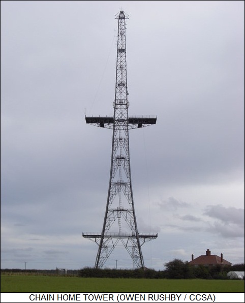
* The stations could be tuned to four different wavelength bands in the range from 15 meters to 10 meters (20 MHz to 30 MHz). The bandwidth could be set to 500 kilohertz (kHz), 200 kHz, or 20 kHz. A CH station did not look like a modern radar station, instead resembling a "farm" of radio towers. There were four (later reduced to three) metal transmitter towers in a line, and four wooden receiver towers arranged in a rhomboid pattern.
The transmitter towers were about 107 meters (350 feet) tall and spaced about 55 meters (180 feet) apart, with cables strung from one tower to the next to hang a "curtain" of horizontally positioned half-wave transmitter dipoles, transmitting horizontally polarized radio waves. The curtain included a main array of eight horizontal dipole transmitting antennas above a secondary "gapfiller" array of four dipoles. The gapfiller array was required because the main transmitter array had a "hole" in its coverage at low angles. The operator could switch between the two arrays as needed.
The transmitting antenna arrangement not only simplified construction, it was also felt that a horizontally polarized wave would give a better indication on an aircraft, which was a horizontal target when in normal flight. The output stage of the transmitters used special tetrode "valves" (vacuum tubes) built by Metropolitan Vickers of the UK that were water cooled. An air pump system was used to maintain a vacuum in these valves, permitting them to be opened up so the filaments could be replaced when they burned out. A complete backup transmitter unit was provided to ensure that the radar stayed in operation at all times.
The wooden towers for the receiving arrays were shorter, about 76 meters (250 feet) tall. Each wooden receiving tower initially featured three receiving antennas, in the form of two dipoles arranged in a cross configuration, spaced up the tower. Additional crossed dipoles would be fitted later in the war to deal with German jamming.
The transmitter did not send out a nice narrow beam, instead pouring out radio waves over a wide swath like a floodlight. The direction of the echoes returning to the receiving towers could be determined by comparing the relative strengths of the echoes picked up by different crossed dipoles. Comparison of the receiving strength between crossed dipoles on different towers gave the horizontal angle to the target, while comparison of the receiving strength between the crossed dipoles arranged vertically on a tower gave the vertical angle. Only the two top dipoles on each tower were used to determine the horizontal direction, while all three were used to determine the vertical direction. The receiver design owed much to Watson-Watt's old lightning location system.
The pulse width was very long by radar standards, ranging from 6 to 25 microseconds, which meant a corresponding uncertainty in the range of a target. Even a 6-microsecond pulse of radio energy, traveling at 300,000 kilometers per second (186,000 miles per second), is 1.8 kilometers (over a mile) long, leading to at least that much uncertainty in the range of the target. Pulse power was high, with a peak power of 350 kilowatts (kW) initially, then 800 kW, and finally 1 megawatt (MW).
One of the major problems with Chain Home was false or "ghost" echoes from distant, fixed targets. If radar sent out a pulse and the echo didn't come back until after the radar sent out a second pulse, then the echo would seem to have come from the second pulse, indicating a target that was very close when it was really a long ways away. To work around the ghosts, a low pulse repetition frequency (PRF) of 25 Hz was used, allowing echoes to be returned from targets up to 6,000 kilometers away before a second pulse was emitted, ensuring that all the echoes from a pulse would be gone before the next pulse was sent out. That was half the British power grid frequency of 50 Hz, which allowed multiple stations to synchronize their pulse broadcasts, reducing mutual interference. The disadvantage of such a low PRF, ridiculously low in hindsight, was that it reduced the amount of energy the radar was throwing out to detect intruders, and correspondingly reduced the radar's sensitivity.
* Although the concept had its clever bits, Chain Home was a dead-end design. The floodlight scheme wasted transmitter power, since only a small fraction of the transmitter beam, if "beam" was exactly the right word for it, would strike a target, much less be reflected back to the receiving antenna. It was also not very accurate. Range detection was good, to within a kilometer or two, but altitude determination was difficult, and azimuth estimates could be off as much as twelve degrees.
To achieve even that much required not only a lot of engineering work but a lot of calibration, with the radar stations tracking RAF aircraft flying on predetermined courses and operators logging the radar observations. Each CH station required its own calibration, and each was eventually provided with a simple electronic analogue computer designed specifically for the task of processing inputs along with the calibration data into something that could be used. The computer was known as a "fruit machine", a British expression for a slot machine; the computer had three rotating switches that were vaguely reminiscent of the three drums on a one-armed bandit. Despite all its limitations, Chain Home worked, and worked effectively, while continued refinements kept it effective for a surprisingly long time.
The RAF took over control of the Chain Home stations from the boffins, and also developed a fighter-control network using radar and observer stations, of which much more is said later. Initial attempts in early 1938 to use the radar system to direct RAF fighters to discreetly intercept airliners didn't go very well, but everyone learned, and CH proved its usefulness during Home Defense exercises in mid-1938. Ground controllers successfully directed interceptors to their targets three-quarters of the time, in both day and night conditions.
CH stations began to be set up overseas as well. Of course that meant that they had to be called "Chain Overseas (CO)" and not "Chain Home", and had some minor differences from CH.
* By that time, Watson-Watt was no longer in charge at Bawdsey Manor. He had been promoted to a high-level technical management job at the Air Ministry in May 1938, and direction of Bawdsey Manor passed on to A.P. Rowe, whose memo of four years earlier had put everything in motion.
Bawdsey staffers were not entirely happy about the change in management. Rowe was not a technical person and was a humorless, no-nonsense type. In considerable compensation, however, he was conscientious with his people and had a high regard for their abilities, if stuffy about the rules. He was also a very efficient administrator, and skilled at organizational politics. Finally, he believed in the unchained exchange of ideas, organizing "Sunday Soviets" where staff could say what they liked and trade ideas, even crazy ones, among themselves and with users in the military services.
BACK_TO_TOP* The inaccuracy of Chain Home led to Eddie Bowen's interest in airborne radar, which he named "Airborne Interception (AI)". CH was able to guide fighter pilots to the general vicinity of intruders, but it was up to the pilots to find and attack them after that. In clear weather the pilots could see intruders easily enough, but the weather in the UK doesn't stay clear for long, and of course the pilots were almost helpless at night. Bowen felt that AI would help them cut through the murk and the dark.
A more experienced engineer might have been reluctant to take on such a job. The electronics for a CH station filled up rooms and soaked up massive amounts of electrical power, and both space and electrical power were at a premium on fighter aircraft. Another problem was that to keep antennas to a size that could be carried on a fighter, the operating wavelength had to be squeezed down to a meter or so. Finally, an AI set was essentially field combat gear, and so it had to be rugged, reliable, and easy to use.
Although Bowen had been forced to set his AI project aside while he hammered out the bugs in Chain Home, he was able to return to it as the stations came on line. His objective was an airborne radar system that would weigh no more than 100 kilograms (220 pounds), consume no more than 500 watts, and use antennas no longer than a meter (3 feet 3 inches).
Initial experiments were conducted in June 1937 with a system operating at 6.7 meters (44.8 MHz), a selection prompted by the availability of a new, very compact and effective, EMI-built television receiver that operated at that wavelength. Bowen modified the receiver for his purposes, installing the kit on a Heyford bomber. The bomber didn't carry a transmitter, instead picking up signals broadcast by a ground station. The receiver system on board the bomber was to pick up the ground transmitter pulses and the echoes and try to make sense of them. Bowen was enthusiastic about the scheme, but it was tricky to get to work, and Watson-Watt told him to give up on it.
However, the idea was basically sensible in itself, if far beyond the technology of the time. Building a "bistatic" radar with separate fixed transmitter and receiver was straightforward, and in fact it was a common configuration for early radars, including Chain Home. Using a fixed transmitter and moving receiver would require capabilities that wouldn't be available in the lifetimes of the Bawdsey researchers.
Bowen went back to the drawing board and managed to put together a full AI set, using miniaturized "acorn" vacuum tubes developed by the Radio Corporation of America (RCA), and operating at 1.5 meters (200 MHz). Some sources claim this initial set operated at 1.25 meters (240 MHz), but if so development quickly switched to the longer wavelength.
Bowen was visiting his parents in Wales when the AI set was given its first flight test in a twin-engine Avro Anson utility aircraft on 17 August 1937. The test didn't detect any aircraft, but spotted a few ships. This immediately turned the focus of the airborne radar project from AI to airborne ocean surveillance, or what was termed "Air to Surface Vessel (ASV)". Watson-Watt quickly proposed that Bowen's airborne radar be used to observe Royal Navy maneuvers, which began on 6 September 1937. Eddie Bowen was part of the flight crew this time, and the tests were highly successful, with the radar finding warships in weather so foul that other aircraft had been grounded.
BACK_TO_TOP* While Bawdsey worked on different radar technologies and the RAF organized the air defense of Britain around Chain Home, the other British armed services were conducting radar development on their own. The division of efforts greatly annoyed Watson-Watt, who wanted to centralize all such research in his own organization.
The Royal Navy had set up their effort at HM Signal School in Portsmouth in 1935, making little progress until a new commandant was assigned to the school in the summer of 1937. Official interest and support increased dramatically, and work on the naval radar, the "Type 79", finally began to converge towards a solution.
Although the Type 79 had originally been designed to operate at a wavelength of 4 meters (75 MHz), development didn't really get rolling until the wavelength was switched to 7.5 meters (40 MHz). Generating signals at that wavelength was less challenging, and it also allowed the Royal Navy researchers to leverage off the same EMI television receiver technology used by Bowen, which they may have learned about through the Royal Navy liaison at Bawdsey Manor.
A prototype version of the Type 79 radar was successfully demonstrated in early 1938. By the end of the year, the Type 79 had been installed on the battleship HMS RODNEY and the cruiser HMS SHEFFIELD. It would be soon fielded on other vessels and be upgraded to the improved "Type 279".
The Type 79 and Type 279 were similar, both using separate transmitting and receiving antennas mounted on their own masts but rotating in synchronization. The antennas were small, resulting in a wide beam, which was adequate for detecting aerial intruders at ranges of up to about 80 kilometers (50 miles), but not so good at targeting naval vessels. It was also not very good at picking up low-flying aircraft.
* The need for more precise targeting led Royal Navy researchers to hastily develop a 1.5 meter (200 MHz) radar, the "Type 286", based on the technology Bowen had developed during his AI work. The initial "Type 286M" used a fixed antenna, meaning the ship had to change direction to point the radar beam. The Type 286M could pick up a surfaced submarine at a distance of no more than a kilometer if the vessel carrying the radar was pointed in the right direction.
In March 1941, a Royal Navy destroyer managed to spot a German submarine at night using the Type 286M and then rammed the submarine, sending it to the bottom. However, that was basically nothing more than a stroke of luck. A "Type 286P" with a steerable antenna would be introduced in mid-1941.
* The Royal Navy was working on a better solution even as the Type 286 was going into service, in the form of a 50 centimeter (600 MHz) radar for naval gunfire direction. A prototype set was available by the end of 1938, and put through successful sea trials in mid-1939. Designs for a production set for surface fire control, the "Type 284", and for anti-aircraft fire control, the "Type 285", were in place in 1940 and were being delivered to the Royal Navy in 1941.
Both the Type 284 and Type 285 used "Yagi" antennas, essentially a row of dipoles of increasing size mounted on a rod, with the beam generated along the axis of the rod. The antennas, which workers also called "fishbones" for their appearance, were arranged at slightly different angles away from the centerline of the radar, with each side driven in an alternating fashion. The returns to each side would be different until the target was on the centerline. This technique, known as "lobe switching", could provide very precise azimuth angles.
Both the Type 284 and Type 285 had horizontal lobe-switching. It is unclear if the Type 285 had vertical lobe-switching, which would have been handy for an air-defense radar.
All radar users learned sooner or later that such a powerful tool was of limited use without the proper procedures in place to make good use of it. Radar was a new thing and the Royal Navy had to learn by doing. At first, the Admiralty imposed strict limits on the use of radar, restricting it to one sweep every five minutes, in order to confound German radio direction finding equipment. Captains soon began to ignore the restrictions since the usefulness of radar outweighed its liabilities, and eventually the restrictions were formally lifted. Resourceful Royal Navy officers began to see the variety of things they might accomplish with radar, and began to organize central electronic command posts on their vessels.
The value of radar would be proven on the night of 27 March 1941, when the British battleship VALIANT and the cruisers ORION and AJAX, all equipped with radar, jumped an Italian force consisting of three cruisers and four destroyers off the southern coast of Greece at Cape Matapan. All the Italian warships, except for two of the destroyers, went to the bottom.
* The British Army also set up their own radar lab in October 1936, sited at Bawdsey Manor, and directed by Dr. E.T. Paris and Dr. A.B. Wood. Their initial work was on a "Mobile Radar Unit (MRU)", which was basically a version of Chain Home that could be bundled up and moved. It used much of the same electronics gear, but of course used transportable masts about 20 meters (66 feet) tall -- instead of the big towers used by fixed-site CH stations -- and operated around 7 meters (42.9 MHz).
The MRU was picked up by the RAF in 1938, acquiring the formal designation of "AMES Type 9" in 1940. British Army researchers then moved on to the development of "Coastal Defense (CD)" sets to direct coastal artillery, and "Gun Laying (GL)" sets to direct anti-aircraft guns and searchlights.
The CD set was based on Bowen's AI work, operating at 1.5 meters (200 MHz). It was operational by the spring of 1939 and went into production soon after. It used a steerable antenna with lobe switching and had much better accuracy, though only half the range, of Chain Home. The CD set was put into service with air defense sites, as well as coastal defense sites, acquiring the formal designation of "AMES Type 2" in 1940.
It was quickly realized that the CD set could just as easily be used to pick up low-flying intruders that would escape CH. In August 1939, on Watson-Watt's recommendation, the Air Ministry decided to install one at each Chain Home station. In the air defense role, the set was known as "Chain Home Low (CHL)", with those used outside of Britain referred to as "Chain Overseas Low (COL)" or formally "AMES Type 5". It could be put on a tower to perform the functions of both CH and CHL. Early models of the CHL had separate transmit and receive antennas, and an A-scope display.
* The GL effort proved less impressive. About 400 GL Mark I sets were made, followed by about 1,600 GL Mark IIs. They were crude radars, operating at in the band of from 5.5 to 3.5 meters (54.6 to 85.7 MHz). They were capable of ranging but not targeting, which still had to be done by eye. The limitations of GL reflected the entire army radar effort. For the first years of the war, the British Army lived up to the stereotype of stodginess that the Air Ministry had transcended.
The GL Mark II did have its fans. When the Soviet Union joined the war against Hitler after the Nazi invasion of the USSR in June 1941, the British would send the Soviets a large quantity of GL Mark IIs. While the Soviets had developed relatively crude "RUS-1" and "RUS-2" fixed-station radar sets and fielded them in small numbers, the GL Mark II was simple, effective to a degree, and far better than anything else the Soviets had. They designated the set the "SON-2", produced a limited number themselves, and were given hundreds of GL.IIs by the British. They would be handed improved Western radars later.
* The South Africans also developed radar in parallel with British efforts. Dr. Basil Schonland, Director of the Bernard Price Institute in Johannesburg, learned about British radar from a highly-placed visitor in 1939. By the end of that year, the institute had developed a working experimental prototype. By March 1940, they had an operational coastal-defense set, designated "JB" for "Johannesburg", ready for service.
The JB operated at 3.5 meters (85.7 MHz) with a peak power of 5 kilowatts, and used a steerable dipole array. It was built entirely from locally-manufactured components. Improved versions of the JB would follow South African forces to the Mediterranean.
BACK_TO_TOP* The deployment of radar as an operational system and not just an experimental toy led the British to confront a problem that acquired the designation "identification friend or foe (IFF)". IFF was just what it said, figuring out who was friend and who was foe, so friends could shoot foes and not shoot other friends.
IFF was a particular problem with aircraft. Picking out a proper target in the sky during a fast-moving dogfight was difficult, and in the First World War all the combatants had developed distinctive national insignia for their aircraft to protect them from friends. Radar greatly compounded the IFF problem, since a target appeared as no more than a featureless blip on a screen. There had to be some way for the radar to perform IFF, and to complicate matters any scheme used should not reveal the aircraft's presence or location to an enemy, or be easily duplicated by an enemy intruder.
Even before the introduction of radar, the RAF had developed a tracking system for directing fighters known as "Pip Squeak", which used direction-finding stations to triangulate the position of a fighter based on a tone emitted by the fighter's radio for 14 seconds out of every minute, unless the pilot was talking over the radio.
The problem with Pip Squeak was that it wasn't easy to integrate with the radar network. It would be preferable to have an IFF on an aircraft that the radar itself could identify. In 1938, Bawdsey researchers had tinkered with a "passive" radar reflector mounted on fighters and tuned to Chain Home frequencies as a means of marking friends. That was supposed to ensure that friendly fighters were brighter to CH than foes, but it was too simplistic an approach. The magnitude of radar reflections depends not only on a large number of environmental factors but on the angle at which the radar beam hits the aircraft, and it proved impossible to consistently determine which aircraft were carrying passive reflectors and which were not. Clearly, a more sophisticated "active" electronic IFF system was needed.
The result was "IFF Mark I", which was the first IFF "transponder". On receiving a radar pulse in the proper wavelength range, it would transmit a response pulse that rose in amplitude, allowing a radar operator to identify it as belonging to a "friend". IFF Mark I went into operation in late 1939, with a thousand sets built. It was triggered by CH radar transmissions. It was, however, difficult to use, since aircrew had to adjust it in flight to get it to respond properly, and it didn't respond properly about half the time.
It was quickly followed by "IFF Mark II", which had been in development even before the introduction of Mark I. Mark II could respond not only to Chain Home signals, but also to 7-meter (42.9 MHz) signals from the MRU, the 1.5-meter (200 MHz) signals of Chain Home Low and Navy sets, and the 3.5-meter (86.7 MHz) signals of Army sets. Unfortunately, though it worked better than IFF Mark I, Mark II was overly complicated and still required inflight adjustments. IFF was a sticky problem and getting to work right was going to take some effort.
Incidentally, the British designation "IFF" has stuck to the technology to this day, probably because it was hard to think of any more sensible name to call it. That partly compensates for the triumph of Yank terms like "radar" and "sonar" over the British terms "RDF" and "ASDIC".
BACK_TO_TOP